Top of R4 & C3 should have their own trace (can be thin, no current going through it anyway) directly to the output pin.
Similarly, the bottom of the ref zener and R3/C4 should have their own track to the output gnd pin.
Jan Didden
Similarly, the bottom of the ref zener and R3/C4 should have their own track to the output gnd pin.
Jan Didden
AndrewT said:
Use a star connected ground point that coincides with the output ground.
And make sure that the output live is also a star connected point that coincides with the output live.
But wouldn't we end with messy nest of traces then?
Rüdiger
That's where the PCB designer gets to show his/her prowess, in both layout skills and understanding what the circuit needs to operate correctly.Onvinyl said:wouldn't we end with messy nest of traces then?
Sorry guys, took a while to get the time to work on this at all. Here is a preliminary layout, basically following what (I think) Jan suggested.
From the schematics this looks to me like back to square 1 .... well let's not quibble, square 1 1/2, but still some points that could have been amended.
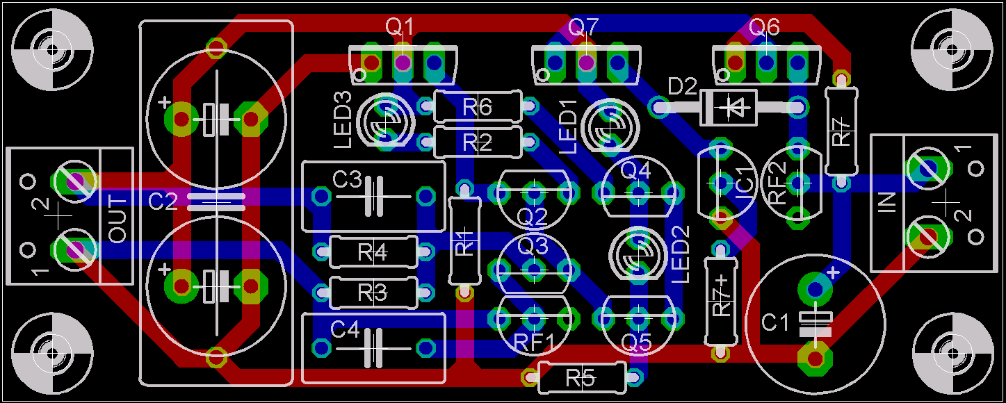
I cannot see the star connected supplies and grounds.
Look at the route from:
C2, R5, Q5, LED2, Q4, LED1, Q7, Q1, C2.
Torturous in the extreme.
Q2, R2, LED3, R6, Q4, share a trace with Q1 and all those other components.
Look at the route from:
C2, R5, Q5, LED2, Q4, LED1, Q7, Q1, C2.
Torturous in the extreme.
Q2, R2, LED3, R6, Q4, share a trace with Q1 and all those other components.
Andrew has a point, but I don't think it is that bad, not all shared tracks cause trouble. We're making progress for sure.
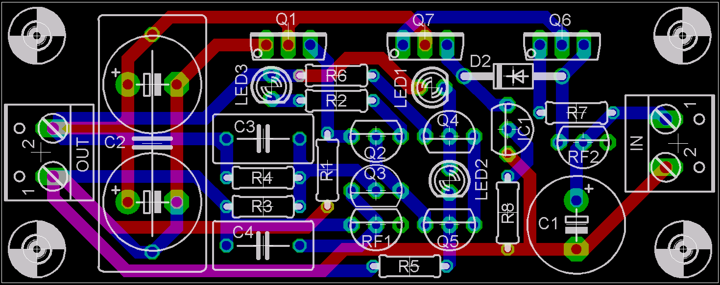
I would make the following changes:
- separate track for R5 to output ground. You can route a blue trace over the existing red trace;
- same for EQ1, and if feasable R1 (you can route bottom R1 in red below R3 to via below C2);
- keep the shunt current out of the board. CQ1 is routed OK, but get R6 and LED1 away from that collector. Give them a separate route to Vout with a blue trace between the two electrolytics. They can share a route.
- There's an unused via above C2 I think.
Let's see how it looks then. 😉
Jan Didden
Hi,
can I suggest something a little different but trying to achieve the same end.
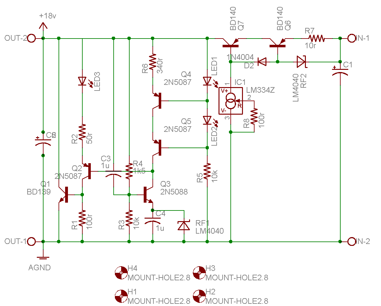
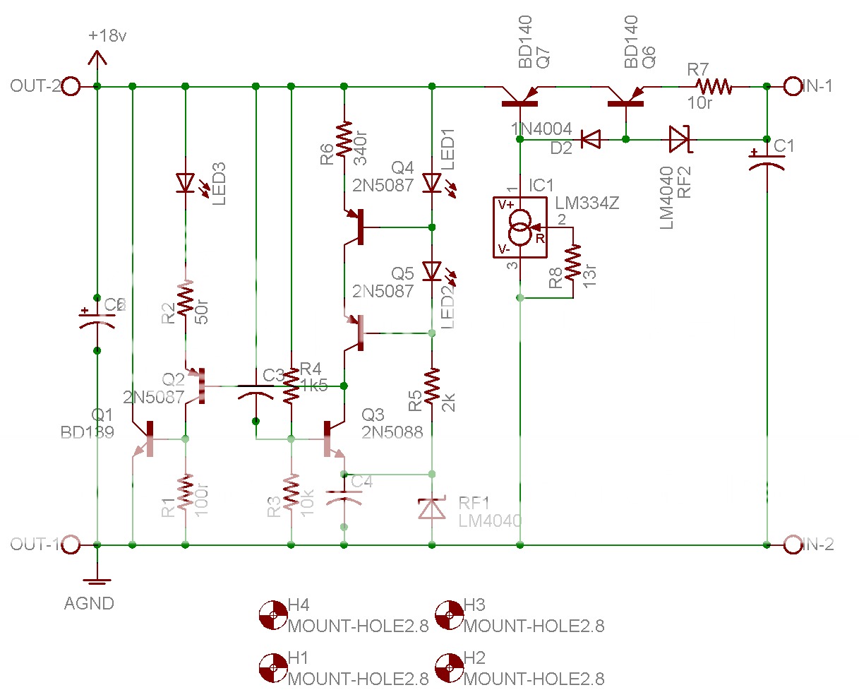
The measuring bridge consists of R4:R3 and R6+Q4+Q5:RF1.
The associated caps C3 and C4 must stay with the measuring bridge.
Similarly, LED1+LED2+R5 must stay with the CCS.
Look at C3, R4, R6 and LED1. The top ends must all coincide.
Look at R3, C4, RF1 and R5. The bottom ends must all coincide.
Take these two coincident junctions, using separate traces, to the two output nodes.
The highest variable current is through Q1. Take it's collector and emitter, using separate traces to the two output nodes.
That leaves CQ7 and LED3 to go to output node and IC1 and R1 to go to the other output node.
I think C2 should connect as close as possible to Q1 C & E. Or should C2 go to the output nodes?
I can't get my head around this last link.
can I suggest something a little different but trying to achieve the same end.
The measuring bridge consists of R4:R3 and R6+Q4+Q5:RF1.
The associated caps C3 and C4 must stay with the measuring bridge.
Similarly, LED1+LED2+R5 must stay with the CCS.
Look at C3, R4, R6 and LED1. The top ends must all coincide.
Look at R3, C4, RF1 and R5. The bottom ends must all coincide.
Take these two coincident junctions, using separate traces, to the two output nodes.
The highest variable current is through Q1. Take it's collector and emitter, using separate traces to the two output nodes.
That leaves CQ7 and LED3 to go to output node and IC1 and R1 to go to the other output node.
I think C2 should connect as close as possible to Q1 C & E. Or should C2 go to the output nodes?
I can't get my head around this last link.
Hi Andrew,
If all works well, there is pretty much zero current through C2. It is in parallel with fractional ohms impedance. Even at 20kHz, C2 (assume 10uF) as a pure cap has still some 0.8 ohms, and it's ESR is probably a multiple of that. Its task is to stabilize the loop, some impedance (tracks) only help here, so I think the exact connections of C2 are not that critical.
Your other recommendations seem sensible, if they can be accomodated without blowing up the pcb. And once you have correctly connected the bridge you get into diminishing returns.
Jan Didden
Hi,janneman said:, if they can be accommodated without blowing up the pcb. And once you have correctly connected the bridge
most do not seem to realise that nearly all of these regulators (both shunt and series) rely on a measuring bridge and that the bridge must not be compromised.
The difficult part will be getting it all to fit in the area that is available.
That was a major plus feature of this design. 4PCBs for the cost of one. My order looks as though it's going to rise to 38PCBs if we can keep the area/costs down to the original estimates.
I'm considering breadboarding the design, but I have never tried your measuring method for estimating the effectiveness. If I can't rely on "my results" then there is no point in starting the breadboard exercise.
Would you be able to elaborate on the test method if I go the experimental route and get weird results?
On measuring Zout: you need a signal generator and a sensitive millivolt-AC voltmeter that goes to at least 20kHz.
You connect the signal generator output to the output of your supply via a capacitor to block the DC, and via a resistor of say 500 or 1000 ohms. Make sure the cap and R (which form a high-pass filter of sorts) are flat to your lowest freq point you want to measure.
The lower R value gives more sensitivity but not all signal gens can drive low value loads. Then connect the mV meter directly across the supply.
Calculate the test signal current into the supply, assuming that the supply is a perfect sink. Suppose your signal gen Vout is set at 10V RMS, and you use 500 ohms series R, that gives 2mA signal current. You measure on the mV meter 1mV. Then, ohms law says that the supply Zout = V/I in this case 1 *10^-3 V / 2* 10^-3 A = 0.5 ohms. OK?
Now you see that the critical item is the mV meter. If your supply had 0.05 ohms (50 milli-ohms) Zout, you would have measured only 0.1mV. Some supplies have 10 milliohms or less Zout at low freqs....
You can do this at several frequencies, each time verifying the signal gen output level as it may vary with freq. You can then manually draw a graph or type the numbers into MS Exel and let Bill Gates do the drawing 😉
Jan Didden
Thanks,
I seen you post this before.
I just hope I can reproduce the results you have found. Or will Cetoole's simulated results jump out at me?
I seen you post this before.
I just hope I can reproduce the results you have found. Or will Cetoole's simulated results jump out at me?
That looks great Colin and quite compact layout but of course we will wait for other opinions too.
BTW, what’s the size of the board at this point?
BTW, what’s the size of the board at this point?
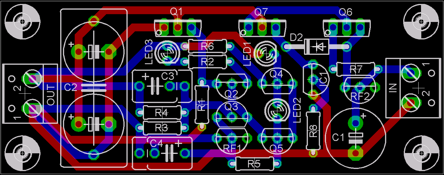
Hi Colin,
Just to please the eye could you rotate anticlockwise IC1 and place it in line with Q2/Q4, then move RF2 to right a bit and rotate clockwise and rotate anticlockwise R7 and place upper end of R7 below Q6 and in parallel to D2.
Just to please the eye could you rotate anticlockwise IC1 and place it in line with Q2/Q4, then move RF2 to right a bit and rotate clockwise and rotate anticlockwise R7 and place upper end of R7 below Q6 and in parallel to D2.
could the lengths of those star connected traces be reduced substantially by moving the output terminals to near the centre of the PCB?
Yes it could, but I wouldn't expect any measureable improvements. The star routing of the sense bridge (I like your term, very apt) sort of cancelles any tracking influence anyway. And don't forget, we now have a 'perfect' supply at the output pins, but a lot depends on how long and low-impedance the wiring from the output pins to the load is. That will dominate.
This latest layout looks pretty good to me. There is one change I would make to the circuit (and the layout) and that is to run the bottom of R5 into the top of RF1 instead of to gnd. That will make the current into RF1 less dependent of the current in Q3, further lowering Zout.
What's the current in IC1? You want some hefty current in there so as not to make it too much dependent on the base current requirements of Q7. With the 100 ohms it is probably less than a mA; I would got to at least 5mA (13 ohms or so IIRC).
Jan Didden
Jan Didden
- Status
- Not open for further replies.
- Home
- Amplifiers
- Solid State
- Bipolar discrete shunt regulators