Is your source for SQ wave, a 50ohms impedance?
If so, then you need a 50ohms load at the end of the cable to see a clean SQ wave coming out of the cable.
That 50r is added across the input to the DUT.
Now measure the SQ wave at the DUT input and see what you are inputting.
If so, then you need a 50ohms load at the end of the cable to see a clean SQ wave coming out of the cable.
That 50r is added across the input to the DUT.
Now measure the SQ wave at the DUT input and see what you are inputting.
Thanks AndrewT.
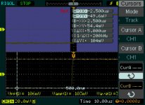
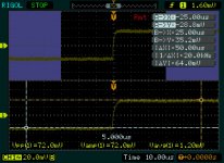
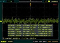
Attached are two shots of the square wave across a 51 ohm resistor attached to 1M cable. The wiring is not shielded.
The first is the calibration point from an old HP1741A scope. The second is from the Rigol DS1102E.
The first looks pretty good to me, especially with the 100mVpp output.
Attached are two shots of the square wave across a 51 ohm resistor attached to 1M cable. The wiring is not shielded.
The first is the calibration point from an old HP1741A scope. The second is from the Rigol DS1102E.
The first looks pretty good to me, especially with the 100mVpp output.
Attachments
Here we are with the QA400 views of the Left and Right channels of the F5T. No real significant difference between the two.

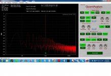
And finally noise from each channel with inputs shorted.
It appears the issue is with sensing using the QA400. The resistor ladder must be picking up the noise as EMI.
Is there any point to continue this investigation?
It appears the issue is with sensing using the QA400. The resistor ladder must be picking up the noise as EMI.
Is there any point to continue this investigation?
Attachments
Considering that for the QA400, +3dbV is 0 dBFS = 1.414 Vrms, then 1mVrms is -63 dBFS or -60dBV which is what the QA400 is claiming to be the case.
I guess the next step is to check the power rails as bear has requested.
I guess the next step is to check the power rails as bear has requested.
Left and right channels INPUT SHORTED??
Can you test this? Using the QA.
Among thing that need to be ascertained is if the "pollution" tracks the output level or not...
...assuming that the signal level coming out of the amp is high enough so that the naturally occurring noise floor is sufficiently
low.
_-_-
Can you test this? Using the QA.
Among thing that need to be ascertained is if the "pollution" tracks the output level or not...
...assuming that the signal level coming out of the amp is high enough so that the naturally occurring noise floor is sufficiently
low.
_-_-
Last edited:
@AndrewT -- termination is unneeded at 1kHz; no significant errors will show up at low bandwidths. Testing at 50+ MHz, yep, terminate please. Of course it doesn't hurt.
@bear and BigE -- please consider that the Rigol's vertical resolution is probably 8 bits -- the noise on the square wave output from the cal out could be? is? ADC noise.
@bear and BigE -- please consider that the Rigol's vertical resolution is probably 8 bits -- the noise on the square wave output from the cal out could be? is? ADC noise.
@bear... in the previous screenshots, the inputs were shorted.
These are the results of checking the power rails for the left channel.
The purple is the POS + NEG rail signal. The probes had their ground clips removed. The speakers were connected, but the inputs were shorted. Disconnecting the speaker does nothing.
The common mode noise appears to be quite high.
Which suggests that the wiring from the transformer to the cap bank is not good, or the wiring from the cap bank to the output boards.
Attachments
Last edited:
I think the QA190 and/or the QA400 ground needs to be connected to the amp chassis. What's the upper yellow trace? You can plainly see the scope's ADC resolution in the dithering of the noise signal in the purple trace... looks like 4-bits to me... So where it says Math scale = 1V, does that mean the purple signal is 1V per major division on screen? I ask, 'cause I haven't used one of these scopes.
Yes, the purple is 1V per division on the screen. The yellow trace is CH 1, CH2 is occluded by the mass of measurements. The yellow labels are CH1, the blue are CH2. No detailed measurements are provided for the MATH trace.
The math trace jumps around from 800 mV to 1600 mV. Since the math trace is CH1+CH2, it can only operate with the resolution of the CH1/CH2 samples.
The vertical resolution of the scope is 8 bits. Those 8 bits cannot include a sign bit, else there would be only 7 bits of resolution.
Now, on an 20V scale, there is +/- 80V on the screen, but the Rigol will happily place the lines off screen for larger signals. It appears that when the vertical scale is 20V, the math trace can show jumps of 400 mV or 0.4 volts -- never any smaller like 200mV or 100mV.
Given that this noise ought to be non-correlated, we can infer that +/-255* 0.4 volts or +/-102 volts can be represented on the 20 volt scale. That sounds about right to me, and explains why the math sample makes the noise look like square waves.
It does not look like the math output gets scaled with the AC coupled signal, but stays at the original 0.4 V/sample size.
Attachments
Last edited:
OK, thanks for the clarification. We don't care much about really LF or DC noise, so AC coupling and the higher resolution is what's wanted here. I suggest looking at the AC ripple and noise on each supply, and see if they make sense to you RE the differential noise between the rails. I don'ty think your output noise issue is due to crap on the rails -- your amp shouls have some power supply rejection (PSRR in spec sheets) and that should help reduce noise at the output.
I normally would expect an audio power amp to have a few millivolts of noise on the output with inputs shorted, usually power-line related 60Hz and 120Hz stuff. Seems like you may be in that area with the F5... A quick verification of the actual noise you have might be useful. No need fretting about the inevitable.
I normally would expect an audio power amp to have a few millivolts of noise on the output with inputs shorted, usually power-line related 60Hz and 120Hz stuff. Seems like you may be in that area with the F5... A quick verification of the actual noise you have might be useful. No need fretting about the inevitable.
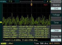
Ok. So I got a pic of the noise, using the Rigol as a differential probe -- no ground reference at the probes, CH1 = Spkr Hot, CH2 = Spkr Return.
The first attachment is CH1, Invert(CH2) and math = CH1 + Invert(CH2). Both inputs are shorted.
The is some spiking, the frequency of the common mode noise looks like 1200nsec => 833 KHz.
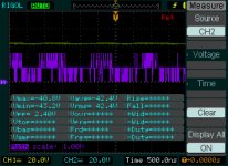
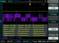
The second shows just CH1 and CH2. Note the Horizontal scale.
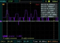
The third is a closeup of the previous math function only.
I think the previous shots showing 2mV noise were done with the wrong probe setting 1x instead of 10x. Now, this does appear excessive.
The first attachment is CH1, Invert(CH2) and math = CH1 + Invert(CH2). Both inputs are shorted.
The is some spiking, the frequency of the common mode noise looks like 1200nsec => 833 KHz.
The second shows just CH1 and CH2. Note the Horizontal scale.
The third is a closeup of the previous math function only.
I think the previous shots showing 2mV noise were done with the wrong probe setting 1x instead of 10x. Now, this does appear excessive.
Attachments


@bear: It does not appear that the noise at the power supply is the same as the noise measured at the outputs.
The output noise has a very high frequency, the noise on the power supply is lower in frequency.
Does the bandewidth of the F5T with 4 pairs per side actually reach 833KHz?
I thought 2 pairs per side goes to 800KHz, 20 pairs to 80KHz and therefore, 4 pairs only to 400 KHz???? How is noise at that frequency even possible -- unless it is being induced on the outputs and not amplified by the amplifier.
Last edited:
I think that the last three images show some key issues... there is obviously common mode noise, but that cancels out nicely. That would be evidence of tightly twisting *some* of the key power supply wiring. The remaining differential noise would be indicative of large loop areas -- the loop being made up of a secondary and it's CT wiring diverging from a twist.
This will be fixed and the final three images will be reuploaded. This is rather big job, but it should be worth it. What ought to happen is that the amplitude of the differential noise ought to go down.
The next step is to reduce the loop area created by my use of the output boards. The architecture I chose to use may benefit from cutting the board traces and distributing +/-/gnd with a twisted braid. However, the use of the speaker protection circuit precludes the final twist of output and speaker return from happening.
Well, all of the fixes you're talking about are for line-frequency noise -- 60Hz and harmonics, 120, 180, etc. The yellow and green -- or is it green and blue -- traces are perfect inversions of each other, and none of what I see is LF line related. You've got other issues, I think, than power supply problems. I have no idea what the phase behavior of this amp is, but it sure looks like something is oscillating.
Well... in the interest of full disclosure, I'm not entirely comfortable with understanding what the scope settings are.
What I'd like to see is the scope ground on PS or speaker out ground, one probe on the + rail and the other probe on the - rail, then the two channels summed, with or without inverting one channel (the one that produces the least total amplitude)
The other point inquired about is seeing if the amplitude of the "pollution" as seen on the QA tracks the amplitude of the input signal - AND if the "pollution" is present with the inputs shorted??
@richem, I suppose an oscillation is possible, but usually they don't span such a wide frequency range. I'm still partial to the local source of that "pollution". Perhaps a SMPS?
10kHz and 20kHz are common SQ wave tests on audio amplifiers.@AndrewT -- termination is unneeded at 1kHz; no significant errors will show up at low bandwidths. Testing at 50+ MHz, yep, terminate please. Of course it doesn't hurt.......
These need and use frequencies around and above 200kHz.
The cable should be terminated to prevent the overshoot that becomes a part of the INPUT signal.
a few one tenths (0.1) of a mVac is more typical for a noisy output..................I normally would expect an audio power amp to have a few millivolts of noise on the output with inputs shorted,............
Less than 0.1mVac is typical for a reasonably noise and hum free output.
Hi Andrew -- you and I come from different generations -- my days in audio began with servicing McIntosh, Marantz, Dynaco, Pilot, H-K, etc, tube gear in the late 50's, so my expectations are built around old-school experience. Of course modern solid-state amps can be much quieter; I also should have stated the noise values I mentioned would be p-p as seen on a scope. I actually forgot the amp in question here is SS and not a big tube rig -- sorry, my bad.
As to square wave testing at 10kHz or more, try looking at the amp (any amp) output with it hooked up to a real load -- a speaker and 3 to 10m of cable, and let me know if anything analytically useful is found. I've done a lot of testing through the years and knowing what an amp can do with resistive/non-inductive loads is helpful to be sure, but the sort of leading edge rundiddlies on a 10kHz square wave output from an unterminated input will usually be small in comparison to the amp's contribution, unless the connecting cable is quite long. Nevertheless, I take your point, especially if the amp in question has exceptionally wide bandwidth, which just can't be a good idea given the loads it will see....
As to square wave testing at 10kHz or more, try looking at the amp (any amp) output with it hooked up to a real load -- a speaker and 3 to 10m of cable, and let me know if anything analytically useful is found. I've done a lot of testing through the years and knowing what an amp can do with resistive/non-inductive loads is helpful to be sure, but the sort of leading edge rundiddlies on a 10kHz square wave output from an unterminated input will usually be small in comparison to the amp's contribution, unless the connecting cable is quite long. Nevertheless, I take your point, especially if the amp in question has exceptionally wide bandwidth, which just can't be a good idea given the loads it will see....
- Status
- Not open for further replies.
- Home
- Amplifiers
- Pass Labs
- BigE's F5T build (Split from QA400)