Ok, dunno if it is just me but on the two images you just posted neither opens to a larger size. They work earlier in the thread and in other threads, not here.
First impression, from the small pix is that there ought NOT be any thickness to the top of the traces.
This is a possible clue. Something is causing that to happen.
You are not showing that noise on the direct connection shown in the earlier trace of the calibrator. So, the question is: is this the noise you are seeing in your amplifier, and where is it coming from??
Use the calibrator signal, the sig gen is not usually a good square wave for these purposes.
The noise is the trim pot. The calibration signal is very clean. I'm just not getting a noise free signal out of the scope. I will try a real resistor ladder and not a trimpot.
Funny about the pics not opening. They open fine here, nearly filling my laptop screen.
This is a shot of the calibration signal output via resistor ladder to knock the voltage down so the amp won't clip. It's a PNG file.
It is amazing just how noisy a trimpot can be.
Funny about the pics not opening. They open fine here, nearly filling my laptop screen.
This is a shot of the calibration signal output via resistor ladder to knock the voltage down so the amp won't clip. It's a PNG file.
It is amazing just how noisy a trimpot can be.
Attachments
Last edited:

Something is amiss.
It is important to know the DC status of that waveform - which flat part is at ground? Or does the waveform go through zero (ground). Most calibrators go from ground up. So if your polarity is inverted that tells us something.
Sure try any equal pair of resistors for example. That will drop you down 6dB.
If you see the same noise and I think you will, then the problem is in your environment.
That expanded view is pretty good but we'd want it extended sufficiently so that the vertical edge has a bit more slope. Then once you get rid of the noise, you test the amp with a properly attenuated signal and observe the same expanded slope.
And, of course re-run the FFT once the noise is gone, if you can find it and eliminate the source.
_-_-bear
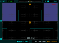
OK, so I got a nice clean square wave by making the resistor ladder very small, and not using alligator clips. Then, when attaching an RCA cable soldered to the resistor ladder, there is noise on the low side of the square wave, but clean tops.
There is 6mVpp of noise on the bottom of the square wave at this point. I suppose a proper signal generator would solve this?
There is 6mVpp of noise on the bottom of the square wave at this point. I suppose a proper signal generator would solve this?
What's the total p-p amplitude of the square wave? 6mV of noise is only important in relation to the whole signal -- by itself it means nothing.
The total amplitude it 0.384 V. So 6/384 = 0.015 or about 1.5% noise. But this is ONLY on the bottom of the square wave.
I have a couple other ideas on how to clean it up a bit.
I have a couple other ideas on how to clean it up a bit.
NOPE. got the bottom clean, but not the top, 25mV out of 160mV ( was wrong about the overall level)
And it just became dirty on both sides.
Sorry, no square wave that is good enough for measurement purposes is going to be happening here anytime soon.
And it just became dirty on both sides.
Sorry, no square wave that is good enough for measurement purposes is going to be happening here anytime soon.
The DDS generators are not what you want for this.
IF you are putting in that noise to the input of the amp, it is going to be amplified.
The question trying to be answered is where is your strange spectrum noise floor in your FFT measurements coming from? Is it inherent in the amp, or being brought in via the inputs, the line and therefore the PS, or is it being picked up via the testing gear??
The "noise spectrum" you displayed is minus how many dB? What level does that correspond to in mV? Is it about what the extra noise on the square wave would result in??
Also, I asked if the square wave was DC to + or DC to - or centered on ground. This way one can tell if the noise is riding on ground or on the non-ground part of the signal.
"Low side" of the square wave on the scope means nothing without the context of the settings of the scope's controls.
In addition, pots are not "noisy" the way this is showing. What is likely being shown is a pick up of external noise.
So, let's nail this down, stop wasting time and effort and determine for once and for all if the noise is in your environment or in some piece of equipment.
ONLY then can you move to correct the problem.
_-_-
Agreed,
The square wave is +/Gnd, not +/-. The bottom of the wave is zero volts.
Now looking at the square wave directly from the scope and BOTH top and bottom are showing about 20mV noise.
And it just stopped being recognized by my laptop as a valid device.
Can't' connect via USB anymore.
The square wave is +/Gnd, not +/-. The bottom of the wave is zero volts.
Now looking at the square wave directly from the scope and BOTH top and bottom are showing about 20mV noise.
And it just stopped being recognized by my laptop as a valid device.
Can't' connect via USB anymore.
I can't use the calibration output as a square wave source. It is too noisy.
The Rigol demo here, DS1102E 100 MHz Digital Oscilloscope | Rigol - Beyond Measure shows the same amount of noise that I have, top and bottom.
The Rigol demo here, DS1102E 100 MHz Digital Oscilloscope | Rigol - Beyond Measure shows the same amount of noise that I have, top and bottom.
Ok, so that issue is removed.
Time to move to the next stage.
(btw, this is another reason that an older but working solid state Tek 'scope is still a good deal)
Perhaps the way to go is to review the suggestions for tests, in the order suggested, and try to do the ones that do not rely upon a clean square wave?
_-_-bear
Time to move to the next stage.
(btw, this is another reason that an older but working solid state Tek 'scope is still a good deal)
Perhaps the way to go is to review the suggestions for tests, in the order suggested, and try to do the ones that do not rely upon a clean square wave?
_-_-bear
Using another scope ( I have an old HP1741A that does not trigger properly) It has a 1V calibration point that gets less than 4 mVpp noise on a resistor ladder that 520 mVpp square wave. Or -42 dB. Even without the resistor ladder, and a 1V calibration signal, the noise is still at 4mV and that makes for -48 dbV.
Not enough.
The noise that is visible on the distortion analyzer is -60 or -70 dB.
Unless that tek scope has noise of below 0.2mV, it's not going to help either.
I will get to the other tasks shortly. Christmas is looming large, and shopping must still get done.
Not enough.
The noise that is visible on the distortion analyzer is -60 or -70 dB.
Unless that tek scope has noise of below 0.2mV, it's not going to help either.
I will get to the other tasks shortly. Christmas is looming large, and shopping must still get done.
BigE, we're not looking for a low noise square wave exactly. My concern was that your squarewave traces showed excessive noise, assuming that they were typical amplitude from the calibrator.
That's why I asked you to be certain to state the exact scope settings.
I have never observed noise riding square waves coming out of my Tek's calibrator, but the RFI noise floor is likely <20mv typically and more like under 10mV usually. It was difficult to tell what the signal levels are/were, but your traces looked atypical.
The purpose of the square waves is not distortion testing but to ascertain (to some extent) the stability of your amplifier.
The rest of what I suggested is to look at what noise may be on your supply rails and to determine if the noise/ripple on the opposite rails cancel or not. Also to try to see if the noise on the output is the same as what is on the rails or not.
bear,
Those traces were just from the scope. NOT from the amp. Sorry, I guess I misunderstood and went after clean traces from the scope.
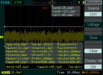
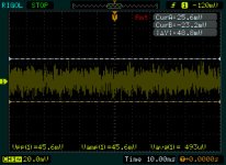
Today, I had company, but we did get one chart out. This is the noise on the Right channel.
X =10 ms, Y=20 mv. The trace is centered at zero here, the reading is AC coupled. Both inputs were shorted.
We also did this, but I did not save, an F5 with inputs shorted( Vpp hovering around 30 mV ) and an AB international class 9620, though the 9620 inputs were not shorted. The 9620 showed about 30-40 mV as well. In all cases, the speakers were disconnected.
The left channel of the F5T was about 10mVpp better. The power supply voltages will be obtained tomorrow. Beer and electronics mix badly.
Those traces were just from the scope. NOT from the amp. Sorry, I guess I misunderstood and went after clean traces from the scope.
Today, I had company, but we did get one chart out. This is the noise on the Right channel.
X =10 ms, Y=20 mv. The trace is centered at zero here, the reading is AC coupled. Both inputs were shorted.
We also did this, but I did not save, an F5 with inputs shorted( Vpp hovering around 30 mV ) and an AB international class 9620, though the 9620 inputs were not shorted. The 9620 showed about 30-40 mV as well. In all cases, the speakers were disconnected.
The left channel of the F5T was about 10mVpp better. The power supply voltages will be obtained tomorrow. Beer and electronics mix badly.
Attachments
BigE, ur a tough audience... suggest you re-read?
We *were* looking for clean square waves from the scope, in order to do a simple test subsequently on the amp.
So, perhaps the next test given what you have done just now is to run the FFT using the QA on each of the amps with the inputs to the amp under test shorted and see what it looks like. Will they have the same residual "pollution"?
OK, that will be done, I admire your patience.
I tried for a couple days to read a clean square waves using very high vertical resolution and short time base. It was not to happen. Odd that the other two old scopes were so very noisy. When the QA400 says the noise is 70 dbV down, then you need a very clean wave.
Where do you get such an extremely clean source? That must cost a few pesos.
I will readjust the resistor ladder on the QA400 sensor. The leads on the resistors are long and may be affecting things. There is a loop area created by the resistor ladder in parallel with the 8 ohm load that can be decreased. I will do this and then post the results. Hopefully the noise decreases as well, which would identify my DIY "sensor" as a problem.
I guess when dealing with signals on the order of 0.2 mVpp the measuring equipment is really put to the test.
Cheers. Will post again tomorrow.
I don't understand why you would pick up the "pollution" you show in your images from the divider. I don't get this at all. I have a simple resistive divider built into two BNC connectors with ground lugs attached by soldering, sitting out in the world, unshielded. You could put the divider in line as I have and then shield it. A box would be classy, but a wrap of aluminum foil might suffice as long as you don't short things out. Etc.
I think you still misunderstand the idea behind the square waves.
And, I still have no clue what the amplitude of the square wave is/was.
Again the idea behind the square waves is to look at the slope of the leading and trailing edges and to see if the amp produces "overshoot" or shows signs of ringing. That's it. Nothing more. All that is needed is a fast, reasonably clean square wave of about 1v p-p. More or less 1v p-p.
Let's ask a question, see what your answer will be? Simple question.
What will the voltage appearing on the output terminals of your amplifier be with the inputs to the amp shorted?
Second question: have you yet looked at the output of each channel of the amp with the inputs shorted??
_-_-
Most of the square wave/resistor ladder combinations I've been trying are about 200 mV p-p. Post 67 states one attempt clearly.
If it is just the leading edge/overshoot we are concerned about, I can generate something that ought to be good enough. I don't think that 4mv overshoot out of 200 is going to be extreme, and it won't happen every time.
If it is the FFT of the square wave showing amplitudes of all frequency components that is of primary interest, then no, the square wave will be so noisy that you will not see the 60 Hz noise components from the amp at -60 or -70 dB.
To answer to your question: the voltage you will see with the inputs shorted will be the DC offset of the amplifier + AC noise (EMI/RFI) in both common mode and differential mode forms, as well as grounding issues.
In my amp the DC offset is less than 10 mV.
The charts on post #76 show the output of the right channel. The left channel looks the same, but has slightly lower peak to peak amplitude -- maybe 10mV less peak to peak.
In that regard, the left channel shows about the same noise as the commercial AB international 9620 amp -- however, the commercial amp did not have inputs shorted. I can't do that, I don't have an XLR to play with -- and it's not my amp.
EDIT.... Wait, you can see the 60Hz noise, given that the noise spectrum is not coherent.... it's not just at 60Hz, it is random. So the FFT will still be OK even with 4mVpp out of 200mVpp!
Last edited:
- Status
- Not open for further replies.
- Home
- Amplifiers
- Pass Labs
- BigE's F5T build (Split from QA400)