Just for reference, my old Tek 7603 with 7A13 Differential Comparator vert amp (100+MHz BW) has about 500uVp-p noise with probes shorted in differential mode, with both 1X and 10X probe settings.
As I see it, at least half your noise is the scope, which is very good to know. I always have wondered what the real noise level is in the Rigol scope; I've wondered about having one to save some room in the lab. But I think I'll hang on to the 7603, the 7A13, the 7A26, the 7A22, the 7S12 sampler, the 7L5 spectrum analyzer, etc, etc....
As I see it, at least half your noise is the scope, which is very good to know. I always have wondered what the real noise level is in the Rigol scope; I've wondered about having one to save some room in the lab. But I think I'll hang on to the 7603, the 7A13, the 7A26, the 7A22, the 7S12 sampler, the 7L5 spectrum analyzer, etc, etc....
I've been thinking about that result... if there were 20mV of noise in the scope, then wouldn't the lines we see would be thicker too, since the noise is at 98MHz?
The noise will be random. That's what noise is.
It is a mixture from 0.000001Hz to 1000000000000Hz.
Your scope circuitry will limit the bandwidth of the noise it presents on screen.
White noise has the same voltage of noise in a fixed frequency band.
i.e. the noise voltage in the band from 1.1Hz to 1.4Hz is the same as the noise voltage from 1234.1Hz to 1234.4Hz.
Pink noise and brown noise are sloped versions (i.e. EQed) of white noise where the noise voltage in equal bandwidths are not the same.
If you have 20mVac of added noise (in the bandpass region of the scope) from the scope circuitry, then that will obliterate much of what you are investigating,
And no wonder why I could not understand what was being posted as scope displays.
Buy yourself an old but working analogue scope. Try for a Dual trace 100MHz going down to 2mV/div or 5mV/div.
If you can only find a 20MHz or 30MHz, then that will be much more useful than what I have seen you using so far.
Last edited:
When evaluating the noise performance of the scope, I just clipped the probes together, not the grounds, since I did not use the grounds on the final few pics. Was that the correct way to do it?
According to the measurements on the scope, there is a max of 12mvPP. This seems huge.
According to the measurements on the scope, there is a max of 12mvPP. This seems huge.
Last edited:
Hmmm. My ground loop breaker has no 100nF cap in it. Could this lack of HF path be the real problem?
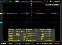
I have been reading about Rigol scopes lately as I'm considering to buy one. Attached 2 screenshots from eevblog.com for a DS1052E:
The probe and cable are picking up noise in the environment, but the scope internal noise is only around ~400uVpp.
- First one shows the noise level (~400uVpp) when channel is shorted with a 50ohm terminator directly at the input;
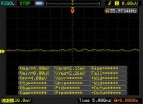
- Second one shows the noise level (~4.8mVpp) when probe is connected and shorted at the tip.
The probe and cable are picking up noise in the environment, but the scope internal noise is only around ~400uVpp.
Attachments
Wide bandwidth and noise go together, and scopes with 1M input Z are quite sensitive to environmental noise from the probes -- EMI, RFI, etc. 400uV p-p at 100MHz is OK -- comparable to 40 y. o. scopes by HP and Tek. I like the features of the Rigol, especially for the price, and I like not being tied to a computer to make measurements, which is why I don't have a USB scope add-on.
Learning how to effectively use a scope can be a pretty intense process, but the rewards are real.
Learning how to effectively use a scope can be a pretty intense process, but the rewards are real.
My noise measurement was wrong -- probe switch and scope did not agree ( noise reported incorrectly at 10x higher value ). I get the 4.8mVpp now.
Just for reference, my old Tek 7603 with 7A13 Differential Comparator vert amp (100+MHz BW) has about 500uVp-p noise with probes shorted in differential mode, with both 1X and 10X probe settings.
As I see it, at least half your noise is the scope, which is very good to know. I always have wondered what the real noise level is in the Rigol scope; I've wondered about having one to save some room in the lab. But I think I'll hang on to the 7603, the 7A13, the 7A26, the 7A22, the 7S12 sampler, the 7L5 spectrum analyzer, etc, etc....
Well you're not missing anything. Digital scopes are good for digital lousy for analog. They will do maths for you but then you'd be hopeless with an analog scope.
I'll keep my Tek 7613.
Now we can move past the PS as a possible source?
So, how about the three tests to see if the QA measures the same "pollution" levels as the signal sent to the amp goes from "shorted input" to mid level, and finally, near clipping?
Again, either do the same thing for both channels, or else short/ground the unused input.
_-_-
So, how about the three tests to see if the QA measures the same "pollution" levels as the signal sent to the amp goes from "shorted input" to mid level, and finally, near clipping?
Again, either do the same thing for both channels, or else short/ground the unused input.
_-_-
If you don't need storage, the 7603s are often below $100, sometimes with some plugins. Best value in the world, if 100MHz will do. I got my 7A13 for $35, the 7A22 for $40, a 7B53 timebase for $25, etc, etc. The 7L5 was $275 -- some are worth more than others. All were working but did need clean up and cal.
Now we can move past the PS as a possible source?
So, how about the three tests to see if the QA measures the same "pollution" levels as the signal sent to the amp goes from "shorted input" to mid level, and finally, near clipping?
Again, either do the same thing for both channels, or else short/ground the unused input.
_-_-
So what about the shots from post #118?
To me that looks like HF power supply noise, is riding on all the secondaries and the center tap.
I'm not near the amp now, but I think that a solution to this noise is one of two paths ( or both ):
Solution A:
1) Add 100nF cap to ground loop breaker to provide a path for this HF noise from the zero volt line to earth.
2) Replace the resistor in each CRC supply with an inductor.
Solution B:
1) Reduce loop area between diode bridge and filter caps
2) *Possibly* reduce loop area in power bus feeding output boards and FE board. ( This is really difficult )
Does this seem like a reasonable idea? .
Regardless, I'm not able to do anything until the New Year.
I'm ready to go past the PS as a probable source for now.
Would greatly like to see the AMP driven by the QA and measured by just the QA, in three situations:
-input shorted (both channels)
-input 10-15dB down from clipping
-input -3dB of clipping
The QA can measure both channels simultaneously and display them together or separately.
The display of the input shorted for both channels may tell if the same noise is appearing on both channels.
But the main thing being looked for is if the pollution remains constant with level, and is present with the input shorted or not.
It might be useful to clip an 8 ohm resistor to each channel of the QA, with the amp powered down but physically near the binding posts of the amp and see what the residual looks like - will it be the same pollution or not??
From where I sit the residual on the PS is fairly meaningless, and may not even be in the PS, but may be environmental noise.
Can this be tried??
_-_-
The QA400 has a limit of input voltage of about 4Vpp, so no, I can't throw 40 Vpp at it.
There are many examples of shorted/not shorted inputs. There is no difference. In my opinion, the HF noise is from the snubbed transformer, and needs an inductor on the rails and a capacitor on the ground loop breaker to remove. The nature of this noise will be checked with an analog scope in the new year.
The low frequency noise that is detected by the QA400 is probably due to massive loop area, from two sources....
One is my own lack of coupling/twisting\ the CT to the secondaries on the input side of the power supply cap bank.
The second *huge* loop area is created by the output boards themselves. On the output boards, the supply voltages and returns are very far apart. The power distribution runs from the front panel of the amp, where the power supply caps are located to the rear panel of the amp, where the front end boards are located along these traces.
To get the power from the front to the back, I run it along the output boards. This is very much less than ideal due to the spacing of the traces on the output boards. To reduce the loop area here, I am considering creating a big fat twisted wire bus, containing all +/-/GND/GATE/Output signals.
Each of the +/- /Gnd/ Gate/output would be connected to the appropriate MOSFET.Diode pair. To reduce the loop area created by the gate/output and GND to and from this "bus", the GND would go out with the gate, and return with the output signal. The output boards would have all traces cut between the two MOSFET/Diode pairs.
In effect, I would be turning the output boards in to two very small PCBs that hold ONLY the MOSFET and DIODE pairs (along with the source resistors and the rest....)
But, before undertaking such a HUGE job, I'd like to be able to determine if the noise can be eradicated by other means.
First step is to verify the precise nature of the noise with a more appropriate scope.
Last edited:
You don't need to throw 40vpp at the QA, use the attenuator/pad set up.
I am not asking about shorted VS. non-shorted input measurements, I am asking about pollution noise vs. output level.
Also, there may be a difference between testing the amp out in the open vs. fully enclosed in a grounded enclosure. Is the amp open or enclosed in a grounded enclosure?
A picture of this amp would be nice, did we see one yet? I don't recall it.
The routing you describe seems unecessary - but without seeing what the situation is, it becomes impossible to know.
Either everyone else with an F5 has this problem, or else you have a uniquely generated problem. It's likely that the latter is the case.
You do NOT want the gate and output signals anywhere near each other.
The power supply and the signals; input, gate, output, etc. should be as electrically and magnetically separate as you can manage to make them.
I'm not sure what this idea of "loop area" exactly is or how it pertains to your particular layout. Again some images of the amp and where things are would help greatly, and likely result in a much faster as simpler resolution than what's going on now. At least that's how it seems to me.
_-_-
Also, how about trying that "test the 8ohm resistor"? If you find the same noise on the 8ohm resistor, that kinda changes things?
- Status
- Not open for further replies.
- Home
- Amplifiers
- Pass Labs
- BigE's F5T build (Split from QA400)