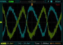
The inputs are shorted. All charts are referenced to speaker output.
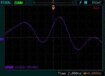
All are AC coupled, so any differences in rail voltage are not reported. All vertical scales are 20 mV. time scales of 1 and 2 are 2ms.
1) positive and negative rails
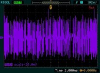
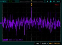
2) math = Pos + Neg
The period of the largest component of rail noise is clearly just over 16 mSec. The period of a 60 Hz wave is 16.67 mSec. So the large excursions of the rail noise are ripple.
It is the noise riding on top of that ripple that is of concern.
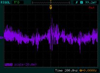
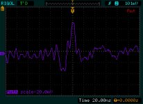
3,4,5 etc... different time scales: 2ms, 200ns 20ns, 2ns, 2us
The point here being that it seems that the 20ns screen capture shows the snubbed ringing and decay of the transformer in response to diode operation, though that looks like a period of 60ns or Freq of 1.6 MHz, which was not the expected value. Perhaps the snubber ought to be adjusted?
The 200ns window is periodic, like the main ripple, showing a period of about 1100ns (90 KHz). That is yet another issue.
The first may be due to a lengthy decay of the ringing transformer.... that can be mitigated with an inductor. ie, CLC vs CRC. I do have 4 pieces of 4.5 mH inductors for the job.
The second at higher frequencies may be oscillation. I had added some bypass caps on the output boards, 330 uF at 50V where the "optional" caps are located on the DIY store boards. These are NOT the 1nf anti-oscillation caps. Those are also present. The thinking being these would provide current for shorter duration peaks. They ought to be removed in the even that they are causing the oscillation.
Does that analysis and plan of work seem reasonable? Does it seem best to remove the bypass caps on the output boards first? Is there some other way to rid the oscillation?
THANKS.
EDIT: I should mention, that these were done while biasing, so the amp had meters installed on two channels. The bias was set to just under 0.300V or approx 90 Class A Watts RMS. It's a big amp.
All are AC coupled, so any differences in rail voltage are not reported. All vertical scales are 20 mV. time scales of 1 and 2 are 2ms.
1) positive and negative rails
2) math = Pos + Neg
The period of the largest component of rail noise is clearly just over 16 mSec. The period of a 60 Hz wave is 16.67 mSec. So the large excursions of the rail noise are ripple.
It is the noise riding on top of that ripple that is of concern.
3,4,5 etc... different time scales: 2ms, 200ns 20ns, 2ns, 2us
The point here being that it seems that the 20ns screen capture shows the snubbed ringing and decay of the transformer in response to diode operation, though that looks like a period of 60ns or Freq of 1.6 MHz, which was not the expected value. Perhaps the snubber ought to be adjusted?
The 200ns window is periodic, like the main ripple, showing a period of about 1100ns (90 KHz). That is yet another issue.
The first may be due to a lengthy decay of the ringing transformer.... that can be mitigated with an inductor. ie, CLC vs CRC. I do have 4 pieces of 4.5 mH inductors for the job.
The second at higher frequencies may be oscillation. I had added some bypass caps on the output boards, 330 uF at 50V where the "optional" caps are located on the DIY store boards. These are NOT the 1nf anti-oscillation caps. Those are also present. The thinking being these would provide current for shorter duration peaks. They ought to be removed in the even that they are causing the oscillation.
Does that analysis and plan of work seem reasonable? Does it seem best to remove the bypass caps on the output boards first? Is there some other way to rid the oscillation?
THANKS.
EDIT: I should mention, that these were done while biasing, so the amp had meters installed on two channels. The bias was set to just under 0.300V or approx 90 Class A Watts RMS. It's a big amp.
Attachments
-
 CHA and CHB, y=20mV X=2mSec AC coupled.jpg149.8 KB · Views: 166
 -
 chA + chB y=20mV, x=2ms ac coupled.jpg198.9 KB · Views: 164
 -
 chA + chB y=20mV, x=200ns ac coupled.jpg128.6 KB · Views: 150
 -
 chA + chB y=20mV, x=20ns ac coupled.jpg115.6 KB · Views: 157
 -
 chA + chB y=20mV, x=2ns ac coupled_2.jpg108 KB · Views: 157
 -
 chA + chB y=20mV, x=2us ac coupled.jpg146.8 KB · Views: 76
Last edited:
The first image - what I would like to see is the same vertical scale but with the two channels summed with one channel inverted = difference between them. Again same vertical scale.
Offhand there is nothing remarkable here.
So, let's move on?
Next step is to see if the "pollution" rides the input level or is independent of the input level.
So all with the QA alone:
1) inputs shorted
2) some medium input level (dunno maybe 0.1v?)
3) higher level, near 1.0v (within 3-6dB of full amp output)
Let's see what that "pollution" does?
Andrew, it is sufficient to do an empirical test without assuming the need for termination. What is being sought here is the difference between input and output, and not to some high degree of precision either.
So a good dual trace scope looking at the input waveform and the output waveform ought to be sufficient. In addition if there is no overshoot on the input, at the amp and also that looks the same as the direct output of the sig gen, then there is no problem.
This particular amp has no output inductor, so there ought to be nil ringing into any reactive load due to that source.
And again, my suggestion was to look for excess overshoot or ringing on the 1kHz square wave as a possible indicator of instability or parasitic.
_-_-
Bear,
All are the same vertical scale. The firs two are taken from the same trigger event, just split into two parts for clarity.
The second image is the two channels summed -- same vertical and horizontal scale as the first image where the channels are shown without summing.
I'm surprised, is 100 t0 120 mVpp differential noise not important? Is that the tail I am chasing?
As for other possible noise sources, auxiliary circuits that control the timing of the dwell time and thermistor bypass relays are sandwiched in between the two cap banks. Those aux circuits use a 555 timer. Do they spit out a lot of noise?
Bear.
I'm sure there are plenty of QA w/inputs shorted already in this thread. But I can make another. As for 0.1V signal, is that a square wave? I ought to be able to do that and capture it on the scope, as well as on the QA400.
I don't have a monster 200+ watt 8 ohm resistor to simulate a speaker load. If I were to do that, it would have to be with a sine wave and a real speaker -- the speaker I use can handle the load. It will just be over 120 dB in volume.... that is not something I really want to do.
-------
Can I connect the QA190 to the scope?
@BigE -- The basic rail signals and levels look good to me, but the HF noise on the supplies is a little troubling -- you've got huge capacitors with equally huge inductance -- I think I mentioned before that these big supply caps each need to be bypassed with good film caps, say 100nF, and maybe ceramics of say 1nF. This is often overlooked; if you've done this, great; if not, please do it.
One other thing -- if this amp has wide closed-loop bandwidth, say well in excess of 100kHz, then I would bypass the feedback R with enough C to bring the BW down to under 100kHz -- myself, I would choose about 50kHz. If there is some instability, this should help the phase margin.
One other thing -- if this amp has wide closed-loop bandwidth, say well in excess of 100kHz, then I would bypass the feedback R with enough C to bring the BW down to under 100kHz -- myself, I would choose about 50kHz. If there is some instability, this should help the phase margin.
Ok richiem, I will try it bypassed.
It is a CRC supply, built with panasonic caps and dale resistors. Each C is 2 x 22,000 uF caps in parallel, so each C = 44,000 uF ( Each bank is physically CCRCC ). There are four such banks in the amp, one bank per rail per channel.
So, when bypassing with the 100nF and 1nf caps, how many do I use?
One bypass pair (100 nf||1nf) per CC = 8 bypass pairs. Or does each individual cap need a bypass pair = 16 bypass pairs?
I read somewhere that mica makes a good bypass cap. Can I use mica for both?
I hesitate to use bypass caps because of other threads on DIYaudio that warn against using small value caps in parallel with large electrolytics. The suggestion is that the small bypass cap can cause oscillation with the parasitics of the large electrolytic -- exactly what it appears we're trying to cure here.
There are solutions, but they require RC snubbing of the capacitors in the cap bank.
One simple equation I found was for an optimal Cbypass = ESL/(ESR^2).
Which means taking out a cap and measuring ESL.
There are solutions, but they require RC snubbing of the capacitors in the cap bank.
One simple equation I found was for an optimal Cbypass = ESL/(ESR^2).
Which means taking out a cap and measuring ESL.
Ok, BigE, NOT the QA with the inputs shorted, the AMPLIFIER with the inputs shorted.
Then with a mid level signal. (no longer shorted)
Then with a high level signal, maybe 3dB below clipping.
All while measuring with the QA.
-----------------------
Regarding the rails. IF as you say the vertical scale on the display is all the same, then the second image makes no sense, as I see no cancellation, since the peak level seems the same as the sawtooth of the residual ripple?? I must not understand what is being shown.
Again the idea is to show the + & - rails dual trace as you did. Then with the same vertical scale, show them summed so that they cancel each other - usually that requires one channel to be "inverted". Have you done this??
Dick is suggesting you "bypass" or place in parallel with your filter caps some smaller caps that work out to high frequencies. The self inductance of the larger caps tends to make them (to simplify) work less well as frequencies get higher.
I'd suggest that it is so simple to try bypassing that you ought to just try it and see if you find a difference in your measurements.
But first, please try what I am suggesting??
_-_-
Ok, BigE, NOT the QA with the inputs shorted, the AMPLIFIER with the inputs shorted.
yes. Plenty of those shots above..... I will deliver another. But I fear that the next two weeks will have zero activity on my part....
Then with a mid level signal. (no longer shorted)
Then with a high level signal, maybe 3dB below clipping.
All while measuring with the QA.
Of course. But I ask, what sort of signal?
-----------------------
Regarding the rails. IF as you say the vertical scale on the display is all the same, then the second image makes no sense, as I see no cancellation, since the peak level seems the same as the sawtooth of the residual ripple?? I must not understand what is being shown.
The noise on the ripple is very large.
Again the idea is to show the + & - rails dual trace as you did. Then with the same vertical scale, show them summed so that they cancel each other - usually that requires one channel to be "inverted". Have you done this??
Yes.
Dick is suggesting you "bypass" or place in parallel with your filter caps some smaller caps that work out to high frequencies. The self inductance of the larger caps tends to make them (to simplify) work less well as frequencies get higher.
There is no such thing. If caps have inductance, it is due solely to the wire length between the cap and any neighboring component. Specifically, it is the inductance of the wire.
I'd suggest that it is so simple to try bypassing that you ought to just try it and see if you find a difference in your measurements.
But first, please try what I am suggesting??
_-_-
The last post with pics has what you are asking, just spread over two pics for clarity. Both scales are the same. A and B are the two rails. The purple trace is A+B: the differential noise. And yes, the difference is HUGE.
I realize that the techniques of twisting wires and reducing loop area are normally targetting low Hz noise, but why not HF noise?
I will post again in the new year, showing the least reduction of loop area I can manage. If the noise is induced, then decreasing loop area will mitigate it irrespective of frequency.
At least, that is how I see it -- I could be wrong.
-----
I apologize if I am "testy". I probably should not post after 6 pints and 7 shots of Jaegermeister.
Last edited:
BigE -- the filter caps do indeed have self inductance, and the wiring L is trivial in comparison, and completely ignorable unless you are working at VHF -- the caps after all are big wound coils of aluminum foil. In big caps like yours, the self inductance is very large, and above a few tens of kHz their impedance rises very quickly, which works against reducing HF noise.
Each cap should be bypassed, unless the big caps are in series with stabilizing resistors across each. In the case of a series pair, one set of bypass caps around both, from rail to ground.
If you can find mica caps of 100nF size, by all means use them. I use polypropylene film caps for the 100nF and general purpose ceramics for the 1nF, but NP0 or C0G types are the best ceramics. Mica are also very good at 1nF.
Happy holidays to you, and all on this thread!!
@BigE -- The basic rail signals and levels look good to me, but the HF noise on the supplies is a little troubling -- you've got huge capacitors with equally huge inductance -- I think I mentioned before that these big supply caps each need to be bypassed with good film caps, say 100nF, and maybe ceramics of say 1nF. This is often overlooked; if you've done this, great; if not, please do it.
One other thing -- if this amp has wide closed-loop bandwidth, say well in excess of 100kHz, then I would bypass the feedback R with enough C to bring the BW down to under 100kHz -- myself, I would choose about 50kHz. If there is some instability, this should help the phase margin.
Don't bypass electrolytics.Ok richiem, I will try it bypassed.
It is a CRC supply, built with panasonic caps and dale resistors. Each C is 2 x 22,000 uF caps in parallel, so each C = 44,000 uF ( Each bank is physically CCRCC ). There are four such banks in the amp, one bank per rail per channel.
So, when bypassing with the 100nF and 1nf caps, how many do I use?
One bypass pair (100 nf||1nf) per CC = 8 bypass pairs. Or does each individual cap need a bypass pair = 16 bypass pairs?
I read somewhere that mica makes a good bypass cap. Can I use mica for both?
For years we have had many reports with pics of the ringing that occurs when low esr caps are added to the inductance of traces and big electros.
Add local decoupling where the fast current changes are happening. Usually at the OUTPUT devices and at the DRIVER devices.
you are absolutely right the be cautious.I hesitate to use bypass caps because of other threads on DIYaudio that warn against using small value caps in parallel with large electrolytics. The suggestion is that the small bypass cap can cause oscillation with the parasitics of the large electrolytic -- exactly what it appears we're trying to cure here.
There are solutions, but they require RC snubbing of the capacitors in the cap bank.
One simple equation I found was for an optimal Cbypass = ESL/(ESR^2).
Which means taking out a cap and measuring ESL.
low loop area applies to all frequencies.......................
I realize that the techniques of twisting wires and reducing loop area are normally targetting low Hz noise, but why not HF noise?
I will post again in the new year, showing the least reduction of loop area I can manage. If the noise is induced, then decreasing loop area will mitigate it irrespective of frequency.
At least, that is how I see it -- I could be wrong...................
it works for LF and HF and VHF and UHF and even for the GHz of our mobile phones.
yes. Plenty of those shots above..... I will deliver another. But I fear that the next two weeks will have zero activity on my part....
Well then, nevermind that. So, we can assume the "pollution" noise is present with BOTH inputs to the amp shorted, when measured on the QA?
Of course. But I ask, what sort of signal?
the one from the QA. The level is adjustable. Use ur scope to determine level as needed.
-----------------------
The noise on the ripple is very large.
I'm missing something.
The sawtooth in your first picture does not show noise equal in amplitude to the sawtooth. If it was equal or similar the sawtooth waveform would be "swamped" by the higher frequency stuff. To my eye it appears to be <10% of the amplitude. So if the peak value was 20mV, then the residual should be <2.0mV? Is that what is being shown?
Is this what you have?
Yes.
There is no such thing. If caps have inductance, it is due solely to the wire length between the cap and any neighboring component. Specifically, it is the inductance of the wire.
Then why does the capacitive Z increase with frequency, more so with large electrolytics?
The last post with pics has what you are asking, just spread over two pics for clarity. Both scales are the same. A and B are the two rails. The purple trace is A+B: the differential noise. And yes, the difference is HUGE.
So, since I have a hard time telling what ur scope is displaying in amplitude, what is the peak value of the sawtooth, and the peak value of the residual in the second pic?
I realize that the techniques of twisting wires and reducing loop area are normally targetting low Hz noise, but why not HF noise?
I will post again in the new year, showing the least reduction of loop area I can manage. If the noise is induced, then decreasing loop area will mitigate it irrespective of frequency.
At least, that is how I see it -- I could be wrong.
BigE, I think your focus ought to be on identifying the true source of the problem, not "trying things" to see if they work. You might get lucky, but probably not.
Another thing to try is to test the amp all closed up inside a metal enclosure that is grounded.
I'm still thinking that you are picking up something in your environment that is dumping out hash...
Have you connected the QA to some sort of antenna/coil to see what it sees?
-----
I apologize if I am "testy". I probably should not post after 6 pints and 7 shots of Jaegermeister.
Yeah, "test this buddy!"

OK, I will use the QA as a sine wave generator.
The noise is in shot two -- the purple mess. Each horizontal dotted line is 20 mV. There is sometimes 100mVpp, but usually about 60 mVpp. The sawtooth amplitude is +/- 60mv... 120mVpp.
My thoughts on capacitors not being inductors are derived from this thread. Esp. posts 14 and 18.
http://www.diyaudio.com/forums/power-supplies/106648-paralleling-film-caps-electrolytic-caps-2.html
EDIT: HOW CAN THERE BE 120mVpp noise in the A + B trace ? In the sober light of day, this makes *no* sense to me at all. For the signal to have that amplitude, you'd need to see evidence of the sawtooth going near zero *all the time*. It does not.
Last edited:
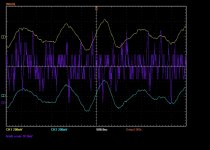
FINALLY! A nice shot of the PS noise. Note the noise is a sensible value. The math scale is 10mv. The ripple scale is 200mV, AC coupled.
OK. That finally is making some sense.
OK. That finally is making some sense.
Attachments
Last edited:
The probes are 10x, they are not referenced to anything -- the GND clips have been removed, so the math function can enable the scope to operate like a differential probe.
The envelope of the noise is 50mVpp, but the actual noise is much lower. I am very keen on seeing what happens when loop area is further reduced. I won't get to it though, due to the holidays.
The envelope of the noise is 50mVpp, but the actual noise is much lower. I am very keen on seeing what happens when loop area is further reduced. I won't get to it though, due to the holidays.
OK NOW, we are cooking:
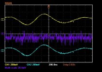
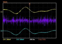
Two shots, outputs and power supply. different times, as I do not have 4 channels. A 4 channel scope is a darn good idea, but 2 channels are better than nothing.
First shot: output voltages. math scale is 20mv, CH1 and CH2 at 200mV. Scope operating as a differential probe, inputs shorted.
Second shod: PS voltages ( +/- rails ) same scales as first shot.
Even the frequencies are in the same ballpark... in the 940KHz range -- which is near the frequency that Quasimodo suggested that the transformer rings at....
One may suspect that the snubbers at fault?
Regardless, it is clearly PS noise that is riding through to the outputs.
Attachments
@BigE -- RE the link for cap bypass issues -- please read carefully what Conrad Hoffman has to say in posts 16 and 19 -- Conrad is the real deal and he does know what he's talking about.
I positively think that the actual construction of the cap majorly influences the ESL and ESR, and so it's no accident that ESL goes up dramatically as C increases. I do agree with Conrad about bypassing at the rectifiers and at the amplifiers. Often it is more convenient, if less effective, to bypass at the electrolytics just due to space. As a side note, few audio designers do the stage decoupling of power rails that instrumentation and RF designers have to do -- something to think about...
The OS-CON caps are really good, but getting enough C and enough working voltage is tough -- so we have your big pig electrolytics. They need to be bypassed. BTW, the equation presented in another post for calculating the desired bypass value ignores the other circuit impedances and is not helpful. My two cents.
RE the noise plots. None of this is audible, so what is actually at stake here? Why pursue some RF noise unless it is inter- or cross-modulating the audio is audible ways? BTW -- If you haven't checked the scope for residual input noise, just short your probes together for the differential measurement at your shown math scale and look at the residual noise -- it may be near what you're seeing, don't know -- never used one of the Rigols. BTW, what's the bandwidth of that scope?
I'll check Conrad's stuff more closely, thanks!
The bandwidth of the Rigol is 100MHz. When shorting the probes together and doing the same math, I get a math signal that is about 20mVpp, at 98 MHz.
The amp noise is at 940KHz.
So it is safe to say then, that the actual noise displayed at the amp is not 40mvpp, but only 20 mVpp? ie, 10mV peak or 7mVrms? This appears very acceptable.
An interesting test would be to install those bypass caps. Does this pose any danger to the amp?
I know AndrewT suggests to only install caps *with resistors* as snubbers. At first glance, it appears that I use the same snubber values as I did on the transformer, just at the output of the power supply.....Or, they can be recalculated, given the frequency of the noise.
Another test that I think would certainly prove that the transformer is responsible for the noise that is being detected is to change the R in the power supply for an L, and make it CCLCC instead of CCRCC. This would be the sledgehammer approach.
Anyway, nothing will be happening to the amp until the New Year.
THANKS to everyone for their help on this project. I *REALLY* do appreciate it.
- Status
- Not open for further replies.
- Home
- Amplifiers
- Pass Labs
- BigE's F5T build (Split from QA400)