OK, I am putting the F5T back together again. Attached are two shots of the "new and improved" wiring scheme, without load. In this scheme, the transformer secondaries and CT are connected to a barrier strip. The barrier strip is used to convert multiple secondaries into a single wires. The barrier strip contains the snubber circuit as calculated using Mark Johnson's Quasimodo.
Also changed is the CT wiring path. The CT wire is wrapped with the secondaries, then proceeds with the secondaries across the diode bridge, across the first set of "power delay" relays, and splits away from the secondaries as they go to the thermistor bypass relay. Instead of following, the CT line goes to the zero volt line of the power supply.
The power supply is disconnected from the audio circuit -- I did not wish to risk blowing stuff up on first re-connection.
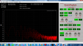
The input "sensor" to the QA400 is a coil of wire wrapped around an iron mill file. This is connected to the inputs of the QA400 with an alligator clip to BNC adapter.
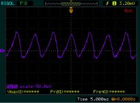
The first shot shows the radiated noise about 8" to a foot from the Right channel diode bridge. The peaks are around -115 dB, higher harmonics at -125 or so with a -130 dB noise floor.
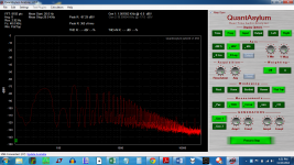
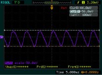
The second shows the radiated noise within an inch or two of the same right channel bridge. the peaks and harmonics are now at about -110 dB.
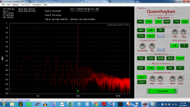
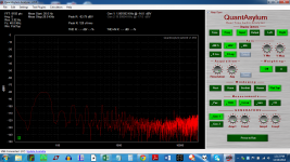
The third shot is for reference ( but with load ) of the noise prior to the inclusion of the snubber and routing of the CT line at about -70 dB.
The next batch will be with load.
Also changed is the CT wiring path. The CT wire is wrapped with the secondaries, then proceeds with the secondaries across the diode bridge, across the first set of "power delay" relays, and splits away from the secondaries as they go to the thermistor bypass relay. Instead of following, the CT line goes to the zero volt line of the power supply.
The power supply is disconnected from the audio circuit -- I did not wish to risk blowing stuff up on first re-connection.
The input "sensor" to the QA400 is a coil of wire wrapped around an iron mill file. This is connected to the inputs of the QA400 with an alligator clip to BNC adapter.
The first shot shows the radiated noise about 8" to a foot from the Right channel diode bridge. The peaks are around -115 dB, higher harmonics at -125 or so with a -130 dB noise floor.
The second shows the radiated noise within an inch or two of the same right channel bridge. the peaks and harmonics are now at about -110 dB.
The third shot is for reference ( but with load ) of the noise prior to the inclusion of the snubber and routing of the CT line at about -70 dB.
The next batch will be with load.
Attachments


With load, the results are not so stellar.
First two shots are new wiring and snubbing vs old wiring no snubbing.
A couple inches away and you get shot 3.
Will have to see next, how the outputs were affected, although the rails are down a couple volts. Perhaps I rewired improperly?
First two shots are new wiring and snubbing vs old wiring no snubbing.
A couple inches away and you get shot 3.
Will have to see next, how the outputs were affected, although the rails are down a couple volts. Perhaps I rewired improperly?
Attachments

Last edited:
left and right channel THD.
A bit depressing. The aux transformer was moved back to the original spot. It did not seem to matter if it was moved around.
A bit depressing. The aux transformer was moved back to the original spot. It did not seem to matter if it was moved around.
Hi BigE -- Don't see any plots...
RE your magnetic pickup -- you'll get better results by using a ferrite rod or a piece of soft (mild) steel, rather than anything hardened, like a file or bolt. I used to use the antenna ferrite rod and coils from an old AM radio. But, whatever works...
You really only care about what comes out of the amp output -- that's where the important stuff happens.
Are these showing the difference/s when you use twisted triplets+snubbing vs any old wiring from transformer to PSU?
When very low load (as in amplifier silent), are you showing a reduction of emitted radiation of ~30dB
On high load when the amplifier is loud, are you showing a reduction of 10dB?
As Rich has asked, can you show the effects at the amp output/s?
When very low load (as in amplifier silent), are you showing a reduction of emitted radiation of ~30dB
On high load when the amplifier is loud, are you showing a reduction of 10dB?
As Rich has asked, can you show the effects at the amp output/s?
AndrewT,
The With/without load is taken as F5T Audio circuit hooked up to PS, vs No F5T audio circuit hooked up. The load being just the bias current.
Below are measurements taken at the business end of things ( the outputs ). The first shot is the left channel, the second is the right.
The With/without load is taken as F5T Audio circuit hooked up to PS, vs No F5T audio circuit hooked up. The load being just the bias current.
Below are measurements taken at the business end of things ( the outputs ). The first shot is the left channel, the second is the right.
Attachments

There is a resistor ladder on the output from which those are taken. The QA400 is hooked up with a banana jack to BNC converter.
I am going to rewire the secondaries to cap bank better. Then, address the actual power distribution. I am not a fan of how far apart the rail and ground voltages are on the output boards and am using those traces as a power/ground bus from the front of the amp (where the cap banks are located) to the rear where the FE board is located.
Instead, I will use a twisted triplet to run at mid height between the N and P boards, and tap into that triplet to feed the output boards. The outputs and gate will remain independent.
The spread between the rails and the grounds may be an issue as they must pass within an inch or so of the toroid.
This will also reduce the zero volt lines going from PS to FE to one. Right now, the zero volt line is split across both P and N boards.
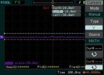
When two channels are used to measure the noise, one being negative, the other being ground, then ac coupling and reporting A(rail) - B(Gnd) I get this sort of noise reported. Nothing that looks like ripple.
FIXED:
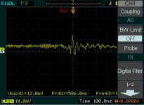
The second shot is ripple,the ripple factor is about 0.24%, where Vripple = Vpp and Ripple factor = Vripple/Vrail.
FIXED:
The second shot is ripple,the ripple factor is about 0.24%, where Vripple = Vpp and Ripple factor = Vripple/Vrail.
Attachments
Last edited:
Cursors added...
So this seems to indicate that the noise is not coming from the power supply. It therefore, must be induced on the input/output, or is a measurement artifact. Shorting the inputs does nothing.
So this seems to indicate that the noise is not coming from the power supply. It therefore, must be induced on the input/output, or is a measurement artifact. Shorting the inputs does nothing.
Attachments
Last edited:

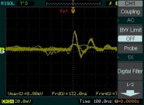
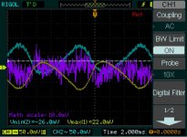
Here are some interesting shots from the scope, taken at the output of the amp.
The first shot is of speaker output. It clearly shows the transformer ringing.
The second short is of the speaker output minus speaker return/gnd. It clearly shows that the ringing is common mode. The cursors are set to show the envelope of the ringing amplitude.
These were taken connected to speaker wire running from the front to the back of the amp. The third shot is take with the scope probe measuring the signal with the return being used for reference. Essentially output - return. Note the scale.... is there problem with power supply noise here?
Attachments
Last edited:
BigE,
I think ur chasing ghosts, or your tail?
Step one:
- look with the scope at only the + rail
- look with the scope at only the - rail
(post results)
Step two:
- add the + and - rail with one channel inverted (if needed) to "sum" the
two and see what the residual waveform looks like.
(this is what the amp, minus any PSRR, will put on the speaker output)
(post results)
Step 2.5:
IF possible use the QA400 (be careful of DC levels and max voltages permitted on the QA400) or the differential box you have to do the SAME TEST but look at the FFT of the residual wavform. (Compare to what the next test shows)
(post results)
EDIT: ur scope likely has a basic FFT function, so give that a shot and show what it produces from this step before
trying the QA, it may be sufficient.
Step 3:
SHORT the inputs of the amp and test with the QA400 what each channel's residual output looks like.
(post results)
Also, please post a picture of what ur scope shows for a 1kHz square wave?
Best if your scope does split time base and you can show the leading edge & overshoot/undershoot in
detail. The digital scope makes it tough to see this with even half of a square wave on the screen.
_-_-
Last edited:
I think I am also chasing my tail. Perhaps the QA400 would prefer to have a USB isolator in between the laptop and the device?
Anyway, pic three is the square wave from the calibration point on the scope.
I posted the ripple before.
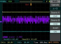
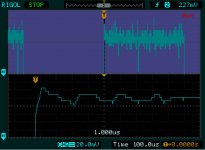
Pic 2 is the DC coupled version, with the purple being A+B, A being +'ve rail, B as -'ve rail and A+B = purple chart signal.
Showing +/- and A+B all DC coupled gives this weird sort of square wave noise -- like some sort of cell phone stuff....
Is this actually there? Maybe I should not leave my wireless phone on the heatsink?
Poic one is the AC coupled view of channel 1 (yellow) channel 2 ( blue) and channel 3: A+B purple.
Anyway, pic three is the square wave from the calibration point on the scope.
I posted the ripple before.
Pic 2 is the DC coupled version, with the purple being A+B, A being +'ve rail, B as -'ve rail and A+B = purple chart signal.
Showing +/- and A+B all DC coupled gives this weird sort of square wave noise -- like some sort of cell phone stuff....
Is this actually there? Maybe I should not leave my wireless phone on the heatsink?
Poic one is the AC coupled view of channel 1 (yellow) channel 2 ( blue) and channel 3: A+B purple.
Attachments
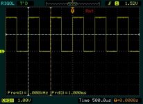
that square wave image shows nothing much since the waves are too small.
what I would like to see is the output of the amp, not the calibrator, per the display description above and in my earlier post?
I'd like to see the leading edge and the top, but only about 10% of that spread across the entire screen.
the first images shows normal and smooth sawtooth ripple. The purple presumably is the subtracted result and is fairly smooth and low in value?
You'd want to do this with the FFT function of the Rigol and/or with the QA to see the spectrum of this stuff, and determine if it matches the garbage ur seeing on the output.
unclear to me what the p-p voltage is in the second image for the purple trace?
but it seems relatively non-nasty.
It is normal to see what is essentially RFI showing up at low levels. You'd need a faraday cage to get rid of that.
Your problem is that there is "garbage" polluting the amps output in your earlier QA graphs.
Suggest you follow the steps I outlined, in the order I outlined, then we will know either what is causing the problem or what is to be ruled out.
The Rigol manual ought to tell you how to look at a portion of a waveform - that's what you want to do to look at the leading edge of a square wave. If you use the calibrator signal as the source (not a bad idea) then you'd want to first look at the calibrator signal this way and then be able to compare to the amps output signal.
Again, it is important to first look at the amps output with both inputs shorted as your reference before doing more tests.
_-_-
It may end up that you need an RFI filter at the input. But this is as yet not clear, it would be useful if you did the steps that I outlined earlier. Then we would have a better idea of what to do next.
Last edited:
Bear, I've been reading about how to get the square waves you want. I think I got it, but have not tried it yet.
I have a very cheap signal generator that is about 25 years old. Will that work?
Otherwise, I will have to put the calibration signal through a resistor ladder or something.....maybe a DCB1 buffer would be best?
Please advise.
I have a very cheap signal generator that is about 25 years old. Will that work?
Otherwise, I will have to put the calibration signal through a resistor ladder or something.....maybe a DCB1 buffer would be best?
Please advise.
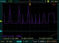
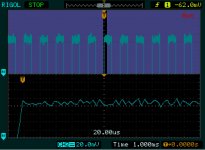
Here is a shot of the cheap function generator output, zoomed in to that vertical division in the lower panel is 20 mV. The upper panel is showing the frequency, in this case 1KHz.
Will this do to drive the amp? It looks to me like the amplified noise will swamp the output.
Will this do to drive the amp? It looks to me like the amplified noise will swamp the output.
Attachments
Last edited:
- Status
- Not open for further replies.
- Home
- Amplifiers
- Pass Labs
- BigE's F5T build (Split from QA400)