The voltage drop across even a dark discharge is not linear with position between the electrodes.
The diodes for my voltage multiplier arrived today, I'm still waiting for the capacitors and the safety resistors. Shouldn't take long to assemble, and I have an old mains torroid that I can use to step up audio and I just need to find some needles and something to use as a grid... 😀
42bit 96kfps Holographic Sound Project
I wonder about the higher voltages we are seing here. My bet is that it would be good
actually to stay within the specs entirely, to get the most direct response according to
input.
Sounds good. And about the torroid, see also my next post.
By the way. The cathode part (including the grid) of a Biefeld-Brown field based transducer
should have a special form / shape, needles are perhaps not ideal.
Nixie said:The voltage drop across even a dark discharge is not linear with position between the electrodes.
I wonder about the higher voltages we are seing here. My bet is that it would be good
actually to stay within the specs entirely, to get the most direct response according to
input.
bigwill said:The diodes for my voltage multiplier arrived today, I'm still waiting for the capacitors and the safety resistors. Shouldn't take long to assemble, and I have an old mains torroid that I can use to step up audio and I just need to find some needles and something to use as a grid... 😀
Sounds good. And about the torroid, see also my next post.
By the way. The cathode part (including the grid) of a Biefeld-Brown field based transducer
should have a special form / shape, needles are perhaps not ideal.
Transformers
Some week ago I discovered that it wouldn't be possible to have a
transformer coupled grid.
Now today, I'll have to say that the above is all Bull.
Transformers have two modes of operation, single-ended and differential.
As long as one doesn't do anything funny with the eventual transformer
center tap, the signal should be single-ended and therefore compatible
with any plasma transducer grid.
Sorry if I confused anyone - My Bad
Floating and fixed zero points
Differential is maybe not the precise word, the meaning is
- something with a 'fixed zero point'.
Differential is maybe not the precise word, the meaning is
- something with a 'fixed zero point'.
I'd think needles would be good because they're an ideal shape to get a very strong electric field around their point that ionizes air molecules.
bigwill said:I'd think needles would be good because they're an ideal shape to get a very strong electric field around their point that ionizes air molecules.
The cathode has the function to 'hold' as much air as possible or needed to
its surface, and then the grid has also much of this function – lesser area here
if placed more towards the anode.
Remember the ions within an atmospheric high voltage field are emitted from the anode

Capacitors have arrived, I have figured out an easy to solder layout for my voltage multiplier, all that needs to be done is a bit of soldering and to get some 10megaohm resistors for safety. (I'm not going to plug it in without these 😀)
I've soldered all the capacitors in my thing up, I need to add the diodes then I should be ready to make ions 😀 I really hurt my back doing that, soldering 30 capacitors onto tagboard in awkward places takes its toll on your when you're leaning over your work 🙁
High voltage measurements
Please post schematics
bigwill said:Capacitors have arrived, I have figured out an easy to solder layout for my voltage multiplier, all that needs to be done is a bit of soldering and to get some 10megaohm resistors for safety. (I'm not going to plug it in without these 😀)
bigwill said:I've soldered all the capacitors in my thing up, I need to add the diodes then I should be ready to make ions 😀 I really hurt my back doing that, soldering 30 capacitors onto tagboard in awkward places takes its toll on your when you're leaning over your work 🙁
Please post schematics
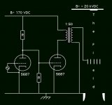
One Audio Pixel
Here is my second take on transformer coupling.
When there is no audio program one could have say a 'new agey' and
otherwise low/silent/attenuated 7.83 Hz wave playing so the transducer
grid is kept at a high voltage compared to the cathode – to keep the transducer
from pumping DC, at full power.
Here is my second take on transformer coupling.
When there is no audio program one could have say a 'new agey' and
otherwise low/silent/attenuated 7.83 Hz wave playing so the transducer
grid is kept at a high voltage compared to the cathode – to keep the transducer
from pumping DC, at full power.
Attachments
Re: High voltage measurements
I basically just built one of these:
http://www.emanator.demon.co.uk/bigclive/ioniser.htm
I don't know how well it'll work 🙂 I'm not sure of the voltage it'll generate but probably around the 20kV range, and I build the large version with 30 220nF caps 😀
Indalhc said:
Please post schematics
I basically just built one of these:
http://www.emanator.demon.co.uk/bigclive/ioniser.htm
I don't know how well it'll work 🙂 I'm not sure of the voltage it'll generate but probably around the 20kV range, and I build the large version with 30 220nF caps 😀
The problem with this design is that it doesn't provide very good regulation, and the voltage will probably change a lot, but it should be good enough to generate ions at a resonably steady rate..
Nixie said:Find an old open core flyback on eBay and build a driver for it.
I will probably do this eventually
I'm about to solder the diodes onto my multiplier and test it out for the first time!
42bit 96kfps Holographic Sound Project
Try to implement the negative section / cathode to get a more directed ion jet. The lifters use
sections of aluminum foil for this.
While enameled magnet wire is used at the emitter / anode.
About using needles for the grid, tip pointed at the anode, and using a bunch of them would
possibly be rather excellent, very aerodynamic 😀
Good luck with the soldering!
I made one of these myself once, it blew up almost right in my face [use glasses for all smoke–tests actually, one should always wear them while working, like the SMD–crew – it is a good thing :d ] – I had two rows running [too close] in parallel on a circuitboard and then there was a flashover between the two 🙄
bigwill said:The problem with this design is that it doesn't provide very good regulation, and the voltage will probably change a lot, but it should be good enough to generate ions at a resonably steady rate..
Try to implement the negative section / cathode to get a more directed ion jet. The lifters use
sections of aluminum foil for this.
While enameled magnet wire is used at the emitter / anode.
About using needles for the grid, tip pointed at the anode, and using a bunch of them would
possibly be rather excellent, very aerodynamic 😀
bigwill said:
I will probably do this eventually
I'm about to solder the diodes onto my multiplier and test it out for the first time!
Good luck with the soldering!
I made one of these myself once, it blew up almost right in my face [use glasses for all smoke–tests
actually, one should always wear them while working, like the SMD–crew – it is a good thing :d ] – I had two rows running [too close] in parallel on a circuitboard and then there was a flashover between the two 🙄I underestimated how long it would take to solder this thing, so I think I need about one more soldering session. My caps are layed out like in the attached image. Some parts of the circuit are worryingly close together and I hope I don't get any flashover! 🙁
Attachments
Aarrgh! I STILL havn't finished this stupid thing! Tommorow it WILL be finished though, as there's so little to do now. So much for doing this on tagboard, it makes this particular thing SO difficult!!
42bit 96kfps Holographic Sound Project
Actually that looks OK to me 🙂 My design was folded and the voltages between the two
rows were much higher than what it is between each cell.
It should be possible to make this more stable by adding a fat? reservoir capacitor and
a lot of high voltage zener diodes connected in series between B+ and the air/ground.
Then again, this is somewhere into the future I suppose.
Here is an alternative PSU http://www.pelletron.com/charging.htm
And what about Neon sign transformers, some of them goes fairly high, maybe >20.
bigwill said:I underestimated how long it would take to solder this thing, so I think I need about one more soldering session. My caps are layed out like in the attached image. Some parts of the circuit are worryingly close together and I hope I don't get any flashover! 🙁
Actually that looks OK to me 🙂 My design was folded and the voltages between the two
rows were much higher than what it is between each cell.
It should be possible to make this more stable by adding a fat? reservoir capacitor and
a lot of high voltage zener diodes connected in series between B+ and the air/ground.
Then again, this is somewhere into the future I suppose.
Here is an alternative PSU http://www.pelletron.com/charging.htm
And what about Neon sign transformers, some of them goes fairly high, maybe >20.
- Status
- Not open for further replies.
- Home
- Loudspeakers
- Planars & Exotics
- 'Biefeld-Brown effect' based full range drivers