Grid Control
With a PWM output the highest value FET I've found is rated 1.5 kV
(Maybe IGBTs also could be used - some have higher ratings, and
they are PWM compatible).
The two Apex op-amps would give almost the double of that. So they
should be easier to work with / give better dynamics. And again, to
make use of these we need an Amplitude Inverter.
By the way, 2 kV may seem little compared to the main >20 kV
of The Field. These 2 kV modulates the higher field so the effect is
>20 ±1 kV.
Software amplitude inversion
The amplitude inversion could also with ease be done all in software, with the
following result / description of an amplitude inverter's function: Loud parts are
attenuated, silent parts are amplified.
And, come to think of it, those Apex op-amps are rather expensive. I've been a
little slow to see the possibility of transformer coupling (one reason is that the
op-amps further on / sometime in the near future somehow appears to be much
'easier' to miniaturize, but maybe one could make really small and high quality
transformers also some day.)
Maybe even slower to see the possibility of connecting a PWM based amp like
the Charlize to a 'ESL ready' / high voltage rated transformer. Again, an amplitude
inversion is needed (please designers; make the PWM chips have a 'single ended'
PWM source output somewhere - for the tweaking plasma purist - life would be so
much easier), [that is] unless one likes listening to amplitude inverted waveforms.
With a good transformer coupling, we won't have the same restriction on the grid
operating voltage either.
Next: How to connect all of this (amp with the associated transformer) to the grid.
bigwill said:What's an amplitude inverter?
The amplitude inversion could also with ease be done all in software, with the
following result / description of an amplitude inverter's function: Loud parts are
attenuated, silent parts are amplified.
And, come to think of it, those Apex op-amps are rather expensive. I've been a
little slow to see the possibility of transformer coupling (one reason is that the
op-amps further on / sometime in the near future somehow appears to be much
'easier' to miniaturize, but maybe one could make really small and high quality
transformers also some day.)
Maybe even slower to see the possibility of connecting a PWM based amp like
the Charlize to a 'ESL ready' / high voltage rated transformer. Again, an amplitude
inversion is needed (please designers; make the PWM chips have a 'single ended'
PWM source output somewhere - for the tweaking plasma purist - life would be so
much easier), [that is] unless one likes listening to amplitude inverted waveforms.
With a good transformer coupling, we won't have the same restriction on the grid
operating voltage either.
Next: How to connect all of this (amp with the associated transformer) to the grid.
42bit 96kfps Holographic Sound Project
What's an amplitude inverter?
With analogy to photography, it makes an exact negative image / print of the waveform.
(about miniaturization, perhaps piezoelectric transformers? http://www.worldandi.com/newhome/public/2004/april/nspub1.asp )
What's an amplitude inverter?
With analogy to photography, it makes an exact negative image / print of the waveform.
(about miniaturization, perhaps piezoelectric transformers? http://www.worldandi.com/newhome/public/2004/april/nspub1.asp )
Indalhc said:What's an amplitude inverter?
With analogy to photography, it makes an exact negative image / print of the waveform.
(about miniaturization, perhaps piezoelectric transformers? http://www.worldandi.com/newhome/public/2004/april/nspub1.asp )
I see. I've had some more ideas of my own for a no-moving parts speaker, although mine is on a bigger scale, not lots of little ones, two big ones for stereo:
An externally hosted image should be here but it was not working when we last tested it.
This is basically an ESL but the "diaphragm" is made from air ions instead. It would be interesting to see if this would work, maybe one day I could try it... I have a feeling these panels might have a good bass response too, since say for example you drove one stator positive and the other negative, you would (I think) get a constant air flow like a fan in one direction, much like a fan subwoofer (unless the accelerated ions lose all their speed when they hit the stators and discharge, would this happen?). A displacement limited diaphragm would not be able to move so much air.
42bit 96kfps Holographic Sound Project
Fan subwoofers operate in class A, as most plasma transducers do.
Except yours d:
Why not?
I have no problem with stereo - as long as it is for prototyping 🙂
(I planned to start working with a DCX, even a DEQX, but after connecting
to this Holographic Sound Project, I found there to be no return 😀
Fan subwoofers operate in class A, as most plasma transducers do.
Except yours d:
Why not?
I have no problem with stereo - as long as it is for prototyping 🙂
(I planned to start working with a DCX, even a DEQX, but after connecting
to this Holographic Sound Project, I found there to be no return 😀
'The Works' again
Here is a suggested transformer coupling of the grid.
(please discard my earlier description on how to make a hardware
amplitude inverter: "invert the wave, then bias everything to reside
below zero". This [first part] may look nice on the paper with a
symmetric sine wave, however it would not give the true inverse
'print' of the wave 🙄
This picture is meant to describe that when the amp gives a/any
load to the transformer / grid, the effect is more and less attenuation.
With no audio signal from the amp the transducer will give full power
(DC).
Therefore, to make normal reproduction of sound, the audio
program must be amplitude-inverted (this applies to transformer
coupling of the grid) (it helps to turn the drawing upside-down while
looking at the waveform's relation to the 'Air-Ground' to get the full
picture 🙂
Attachments

42bit 96kfps Holographic Sound Project
On a second thought - a push-pull operating plasma transducer could be interesting.
And dark pictures are more mild to the eyes, I must incorporate this
bigwill said:
I see. I've had some more ideas of my own for a no-moving parts speaker, although mine is on a bigger scale, not lots of little ones, two big ones for stereo:
An externally hosted image should be here but it was not working when we last tested it.
This is basically an ESL but the "diaphragm" is made from air ions instead. It would be interesting to see if this would work, maybe one day I could try it... I have a feeling these panels might have a good bass response too, since say for example you drove one stator positive and the other negative, you would (I think) get a constant air flow like a fan in one direction, much like a fan subwoofer (unless the accelerated ions lose all their speed when they hit the stators and discharge, would this happen?). A displacement limited diaphragm would not be able to move so much air.
On a second thought - a push-pull operating plasma transducer could be interesting.
And dark pictures are more mild to the eyes, I must incorporate this
That design you quoted looks pretty much the same thing as what Pass did:
http://www.diyaudio.com/forums/attachment.php?s=&postid=23708&stamp=1017889664
As for the previous diagram: why use transformer coupling? This is a perfect example of where direct drive by tubes is what's called for.
http://www.diyaudio.com/forums/attachment.php?s=&postid=23708&stamp=1017889664
As for the previous diagram: why use transformer coupling? This is a perfect example of where direct drive by tubes is what's called for.
Re: 42bit 96kfps Holographic Sound Project
I prefer things to be 'symmetrical', I'm funny like that 🙂 (Apart from where it matters, I prefer the class-A concept amplifiers for example)
That's roughly what I was going to do before I changed my design to push-pull 🙂
I inverted the colours in MS-Paint because after drawing it was hard on the eyes hehe
That looks very interesting, I guess the idea works then. Do you have any more information on these speakers?
Well, either way will work 🙂 I'm not deadly against using transformer coupling as I don't have any valve amps, but If I was to build an amp for speakers like these I would definetely use direct coupling from a valve, providing I could get a big enough voltage swing.
Indalhc said:
Fan subwoofers operate in class A, as most plasma transducers do.
Except yours d:
Why not?
I prefer things to be 'symmetrical', I'm funny like that 🙂 (Apart from where it matters, I prefer the class-A concept amplifiers for example)
Indalhc said:
Here is a suggested transformer coupling of the grid.
That's roughly what I was going to do before I changed my design to push-pull 🙂
Indalhc said:
On a second thought - a push-pull operating plasma transducer could be interesting.
And dark pictures are more mild to the eyes, I must incorporate this
I inverted the colours in MS-Paint because after drawing it was hard on the eyes hehe
Nixie said:That design you quoted looks pretty much the same thing as what Pass did:
http://www.diyaudio.com/forums/attachment.php?s=&postid=23708&stamp=1017889664
That looks very interesting, I guess the idea works then. Do you have any more information on these speakers?
Nixie said:
As for the previous diagram: why use transformer coupling? This is a perfect example of where direct drive by tubes is what's called for.
Well, either way will work 🙂 I'm not deadly against using transformer coupling as I don't have any valve amps, but If I was to build an amp for speakers like these I would definetely use direct coupling from a valve, providing I could get a big enough voltage swing.
42bit 96kfps Holographic Sound Project
I'm not all sure which we are talking about here, but 30 kV would be one heck of a voltage
swing 🙂
We have now many ways of doing this; PWM, transformer, direct drive by valve. Maybe even more.
By the way - came to think of that the 'inverted amplification plasma transducer' works exactly like
a film projector, with its light/lamp full-on if no program [negative] is fed to it.
bigwill said:
I prefer things to be 'symmetrical', I'm funny like that 🙂 (Apart from where it matters, I prefer the class-A concept amplifiers for example)
That's roughly what I was going to do before I changed my design to push-pull 🙂
I inverted the colours in MS-Paint because after drawing it was hard on the eyes hehe
That looks very interesting, I guess the idea works then. Do you have any more information on these speakers?
Well, either way will work 🙂 I'm not deadly against using transformer coupling as I don't have any valve amps, but If I was to build an amp for speakers like these I would definetely use direct coupling from a valve, providing I could get a big enough voltage swing.
I'm not all sure which we are talking about here, but 30 kV would be one heck of a voltage
swing 🙂
We have now many ways of doing this; PWM, transformer, direct drive by valve. Maybe even more.
By the way - came to think of that the 'inverted amplification plasma transducer' works exactly like
a film projector, with its light/lamp full-on if no program [negative] is fed to it.
I don't know much about it other than what was in the thread. Corona wire ionizes air, and is between electrode grids. Pass ended up in the hopsital due to large amount of ozone inhalation.
As for a tube, check out the 3CX300A1, should work well in this application.
As for a tube, check out the 3CX300A1, should work well in this application.
Nixie said:I don't know much about it other than what was in the thread. Corona wire ionizes air, and is between electrode grids. Pass ended up in the hopsital due to large amount of ozone inhalation.
Oh dear

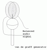
I want to set up the experiment described in the attached pic. Ions from a van de graff generator are moved by an electric field modulated by an audio signal. Will this actually produce much sound? I really want to try it.
Also, another thing, do ion streams like this from a van de graff generator actually generate much ozone?
Also, another thing, do ion streams like this from a van de graff generator actually generate much ozone?
Attachments
42bit 96kfps Holographic Sound Project
I especially like the idea with the VDGGs, for they can go so high d:
Sound, who knows. A lightning can be pretty loud.
If there is a lower voltage limit for ozone generation, maybe there be an upper limit too.
Now, with a push-pull setup there is always an element of 'suspension' / crossover distortion.
bigwill said:I want to set up the experiment described in the attached pic. Ions from a van de graff generator are moved by an electric field modulated by an audio signal. Will this actually produce much sound? I really want to try it.
Also, another thing, do ion streams like this from a van de graff generator actually generate much ozone?
I especially like the idea with the VDGGs, for they can go so high d:
Sound, who knows. A lightning can be pretty loud.
If there is a lower voltage limit for ozone generation, maybe there be an upper limit too.
Now, with a push-pull setup there is always an element of 'suspension' / crossover distortion.
42bit 96kfps Holographic Sound Project
Here follows my third attempt on describing a hardware amplitude inverter.
1) Run the audio wave through an op-amp and bias it so it resides fully in
the negative domain.
2) Then ground its highest point, and 3) run this with its lowest point through
an op-amp [inverter] so that its now most negative part is made the most positive
instead 🙂
It may sound like this could all be done by one inversion at first, however
we would then only have the inverse of the wave, not the inverse of its
amplitude.
I am not necessarily saying the above will actually work however lol
Need some help here still.
Earlier I said a film projector is fed a negative print - I meant to say, the film
source material originally resides in a negative format, and is then being
converted to a positive, for the projector.
With the 'inverse amplification plasma transducer' this can be said to be
very similar, with the difference that the raw material is recorded as a positive
and is then in like manner converted for the playback.
Maybe I could find an amplitude inverter in an old film projector with an optical
audio track?
Also I encourage anyone with programming skills to make a such module, eg
as an Audio Unit. The pay.... This is after all the 42bit 96kfps Open Source
Holographic Sound Project. 😉 Actually, I would pay cash for such a unit.
Phase vs amplitude inversion
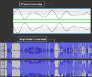
Here is a picture describing the difference between the two.
In phase inversion the whole wave is mirrored against itself.
In amplitude inversion the wave is first split in two halves
then they are mirrored separately against themselves, and
then put back together again.
It should now perhaps be easier to see what an amplitude
inverter should look like. For one, the phase splitting could be
done with a transformer (and by all means, an op-amp could
do this fine also.
Attachments
42bit 96kfps Holographic Sound Project
>>I wrote that in amplitude inversion the wave is first split in
two halves then they are mirrored separately against themselves,
and then put back together again.
It should rather be, the wave is split and then the two halves shift
place with each other.
Have to get back to this sometime tomorrow 🙂
This wouldn't matter much within digital holographic sound, but there
is a pretty interesting inherent noise reduction aspect also here.
Oh my
It looks like I have been trying to feed my single ended plasma transducer
a differential audio signal....
From the present it looks like a transformer coupling of the grid is quite
impossible, naturally 🙄
Anyhow, direct PWM coupling would work just fine, the same with direct-driven valves.
This means, back to square one again, designing a single ended PWM amp from scratch.
- Status
- Not open for further replies.
- Home
- Loudspeakers
- Planars & Exotics
- 'Biefeld-Brown effect' based full range drivers