Work in progress
The need for amplitude inversion.
Amplification means more volts between the anode and the grid/cathode, however when
loading the grid, which can be seen as the ground point of the main power supply (B+)
with a positive charge the overall voltage is then decreased, resulting in attenuation.
I said "direct-driven valves", surely this should be 'direct-driving' instead. And an amplitude
inverter will have to be used in such a setup.
With a single-ended PWM drive of the grid, the effect is that every time the FET gets a pulse
it then grounds the grid to the cathode, this is the same as narrowing the cathode/ground
towards the anode, with a strengthening of the overall field as a result. This without
any amplitude inversion. So the 'inverted amplification plasma transducer' can be said to operate
natively with single-ended PWM audio signals.
Talking about the Van De Graff Generator, such a unit could well be made stabilized (eg by
many zener diodes in series) and work as the main power supply.
I'll take it a little easy forwards with the amplitude inverter, filed for now as 'work in progress' 🙂
One more thing, the reason a transformer coupling of the grid can't work is that this gives a fixed
zero point, while a floating zero point is required instead.
bigwill said:I don't understan the need for amplitude inversion (Couldn't the same thing be achieved with biasing the grid?) and PWM 🙂 Wouldn't a changing electric charge on the grid in proportion with the audio signal work? I think I'm missing something
The need for amplitude inversion.
Amplification means more volts between the anode and the grid/cathode, however when
loading the grid, which can be seen as the ground point of the main power supply (B+)
with a positive charge the overall voltage is then decreased, resulting in attenuation.
I said "direct-driven valves", surely this should be 'direct-driving' instead. And an amplitude
inverter will have to be used in such a setup.
With a single-ended PWM drive of the grid, the effect is that every time the FET gets a pulse
it then grounds the grid to the cathode, this is the same as narrowing the cathode/ground
towards the anode, with a strengthening of the overall field as a result. This without
any amplitude inversion. So the 'inverted amplification plasma transducer' can be said to operate
natively with single-ended PWM audio signals.
Talking about the Van De Graff Generator, such a unit could well be made stabilized (eg by
many zener diodes in series) and work as the main power supply.
I'll take it a little easy forwards with the amplitude inverter, filed for now as 'work in progress' 🙂
One more thing, the reason a transformer coupling of the grid can't work is that this gives a fixed
zero point, while a floating zero point is required instead.
'Gordian' amplitude inverter
I was going to take it easy with this device, and so here is a ez-version;
Record the first playback through the plasma transducer, this recording has
now been amplitude inverted (if its grid was driven with a positive signal),
then play this back once more and we have the original recording again d:
Instead of the recording, one inverted amplification plasma tranducer could
be made 'dual-stage'.
Long time ago, far far away....
Eh, should I
I made an other drawing of the anode - grid - cathode voltages, as they would
appear if the grid was driven directly by valve, any amplitude = attenuation,
unless the plate of the valve was coupled to the air-ground instead of to the grid,
but then that would be problematic of many reasons, safety for one.
By the way, using a Van De Graaff generator we could have a B+ of up to 5 Mega
Volts, I don't think one would see much ozone over there d:
bigwill said:Do you have any pics / sound clips of what you've done so far? 😀
Eh, should I
I made an other drawing of the anode - grid - cathode voltages, as they would
appear if the grid was driven directly by valve, any amplitude = attenuation,
unless the plate of the valve was coupled to the air-ground instead of to the grid,
but then that would be problematic of many reasons, safety for one.
By the way, using a Van De Graaff generator we could have a B+ of up to 5 Mega
Volts, I don't think one would see much ozone over there d:
Attachments
Hear me now
... and believe me later 😀
bigwill said:Do you have any pics / sound clips of what you've done so far? 😀
... and believe me later 😀
Attachments
I'm ordering the parts for a simple low current HV power supply for experimentation. If my idea doesn't work I can always just use it as an air ionizer to clean the air from around our fire.
42bit 96kfps Holographic Sound Project
If this HV PSU should happen to be a Van de Graaff then at its/those obtainable magnitudes
(MV) air appears to move like cogs on a wheel. No much other reaction seems to be going on.
The most recent drawing was of a device we could call a 'dual / non-inverting plasma
valve'. It can amongst other things be used for moving large amounts of air d:
(PS. To clarify and substantiate, the difference between a thermionic and an 'atmospheric' high
voltage plasma valve is that the ions radiates from their cathode and anode respectively)
bigwill said:I'm ordering the parts for a simple low current HV power supply for experimentation. If my idea doesn't work I can always just use it as an air ionizer to clean the air from around our fire.
If this HV PSU should happen to be a Van de Graaff then at its/those obtainable magnitudes
(MV) air appears to move like cogs on a wheel. No much other reaction seems to be going on.
The most recent drawing was of a device we could call a 'dual / non-inverting plasma
valve'. It can amongst other things be used for moving large amounts of air d:
(PS. To clarify and substantiate, the difference between a thermionic and an 'atmospheric' high
voltage plasma valve is that the ions radiates from their cathode and anode respectively)
42bit 96kfps Holographic Sound Project
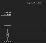
Here is 'The Id' with a thermionic 'preamp' stage.
It would reproduce audio - without the/any amplitude
inverter.
The B+ voltages could be set at different levels,
for example 1kV, 20 kV and 20 kV.
Here is 'The Id' with a thermionic 'preamp' stage.
It would reproduce audio - without the/any amplitude
inverter.
The B+ voltages could be set at different levels,
for example 1kV, 20 kV and 20 kV.
Attachments
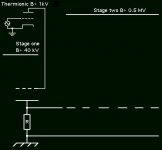
Valves (tubes) and FETs
This following just 'surfaced', that thermionic valves and FET's
have essentially the same function. Connected to an atmospheric
plasma valve the equation is as follows,
A positive audio signal input to the thermionic valve gives a
negative output (grounding) from the same, then feeding this
grounding signal to the plasma grid, the effect is amplification.
So one thermionic and one 'atmospheric' valve stage is all that
is needed.
I'll make a drawing of this sometime soon 🙂
42bit 96kfps Holographic Sound Project
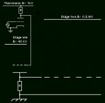
.... that _N Channel_ FETs and thermionic valves have
similar function 🙄
.... that _N Channel_ FETs and thermionic valves have
similar function 🙄
Hmm, very interesting. Are you going to make a prototype like this, or just going through possibilities? I can't wait to start experimenting when I get my HV supply 😀 My dad used to repair lots of valve equipment (amps, radios etc), so we have tons of valves around so I might mess with them eventually (after trying with a step up transformer)
Hopefully I can get this transducer down to at least 100Hz, then it would be really useful.
Hopefully I can get this transducer down to at least 100Hz, then it would be really useful.
I was thinking - is the grounded grid part really needed? The ions would be attracted to the signal grid regardless, since it's very negative/positive compared to the HV source..
42bit 96kfps Holographic Sound Project
I was more into FETs earlier, but without a good single-ended PWM amp it looks like a valve
coupling would work fine - straight out of the box so to speak - only operating at 250 Volts lower than the best FET I could find. And sure, some brainstorming, then the build d:
The 'inverted amplification atmospheric plasma transducer' gives a DC output when nothing is playing 🙂
This is true. Still, a grid is a grid. For example to have a 'directional output' a three grid setup
would be required.
Then again, maybe it would be interesting to also experiment with a grid very close to the anode instead, it could possible work more identical [however reversed] to the grid in a thermionic valve, here again with a negative signal on the grid.
Then the grids would be located more similarly, near their respective emitters.
This could possibly have a much higher effect actually.
bigwill said:Hmm, very interesting. Are you going to make a prototype like this, or just going through possibilities? I can't wait to start experimenting when I get my HV supply 😀 My dad used to repair lots of valve equipment (amps, radios etc), so we have tons of valves around so I might mess with them eventually (after trying with a step up transformer)
Hopefully I can get this transducer down to at least 100Hz, then it would be really useful.
I was more into FETs earlier, but without a good single-ended PWM amp it looks like a valve
coupling would work fine - straight out of the box so to speak - only operating at 250 Volts lower than the best FET I could find. And sure, some brainstorming, then the build d:
The 'inverted amplification atmospheric plasma transducer' gives a DC output when nothing is playing 🙂
bigwill said:I was thinking - is the grounded grid part really needed? The ions would be attracted to the signal grid regardless, since it's very negative/positive compared to the HV source..
This is true. Still, a grid is a grid. For example to have a 'directional output' a three grid setup
would be required.
Then again, maybe it would be interesting to also experiment with a grid very close to the anode instead, it could possible work more identical [however reversed] to the grid in a thermionic valve, here again with a negative signal on the grid.
Then the grids would be located more similarly, near their respective emitters.
This could possibly have a much higher effect actually.
42bit 96kfps Holographic Sound Project
<<The 'inverted amplification atmospheric plasma transducer' gives a DC output when nothing is playing>>
I guess we are past this, since the amplitude inversion problem was solved with a thermionic valve
stage.
Still, also the 'non-inverting' atmospheric plasma valve should be very capable of frequencies all the way to DC.
For my experiments I think I'm leaning back towards a single ended design, as the push-pull design has a few difficuilties which I havn't figured out yet.
Do you think these design will move enough air to make sound?
Do you think these design will move enough air to make sound?
I suppose if the 'lifters' can lift mass on the order of 100g, I guess they can move enough air to produce sound..
bigwill said:For my experiments I think I'm leaning back towards a single ended design, as the push-pull design has a few difficuilties which I havn't figured out yet.
Do you think these design will move enough air to make sound?
bigwill said:I suppose if the 'lifters' can lift mass on the order of 100g, I guess they can move enough air to produce sound..
Sure, the Maximus II does lift 250 grams, and this lift is all pure DC so they should be very able
of producing sound full range in class A.
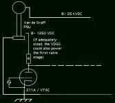
About an eventual anode coupled grid. This is the 'live part' - if a grid was placed very near the
anode, it would probably not need to have a high voltage swing, maybe 250 Volts would
suffice. The grid's power supply could be some battery powered stepped up design only connected/'grounded' by one point to the high >20 kVDC B+. To make a Van de Graaff generator do both the B+'s would be a little complicated - the unit would have to be rather huge (if using a voltage divider with resistors/zeners that is, however there are surely other and better ways of stepping down voltage) 🙄
Actually, a grid coupled to the cathode seems after all to be an easyer way. 1250 Volts should have a fairly strong effect to the higher field.
One thing that puzzles me right now is that I at this moment can't explain what's wrong with an eventual transformer coupling of the grid 😀
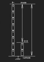
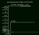
Grid placement
Here is drawing describing voltages within the field.
The grid is placed at about 8 kV, and driven at 1250 Volts so
there are a certain danger for overloads.
In a high current field, a thermionic valve could maybe stand
double its rating safely, perhaps even more.
So with a low current field it could be interesting to start
experimenting with 'low voltage' tubes, for example the 5687.
Attachments
- Status
- Not open for further replies.
- Home
- Loudspeakers
- Planars & Exotics
- 'Biefeld-Brown effect' based full range drivers