I used CLC filtering after the TPS7A4700/3301 on my version of the AD797/BUF634 version.
Is your AD797/BUF634 version AC-coupled on the inputs?
I know the AD797 does not like the changing input impedance if connected directly to the wiper of a volume pot.
Is your AD797/BUF634 version AC-coupled on the inputs?
I know the AD797 does not like the changing input impedance if connected directly to the wiper of a volume pot.
Yes, and there's a resistor in series with the input.
I have not, yet, seen any sign of oscillating such as large DC offset or warm opamp. I don't have the equipment to actually test for oscillation (ie good enough oscilloscope).
Yes, and there's a resistor in series with the input.
I have not, yet, seen any sign of oscillating such as large DC offset or warm opamp. I don't have the equipment to actually test for oscillation (ie good enough oscilloscope).
I figured you would have to add a coupling cap to the AD797's input as well as a 100 or so ohm resistor in series with its noninverting input pin.
Just curious...can you please post(or PM me) a schematic of your AD797/BUF634 circuit for me to review?
My sincere apologizes "X", I'm not trying to derail your BF862 thread.
Your Silicon Harmony Class A HA still gives me those good 'ole wet dreams that results in me having to change my panties in the morning.
FWIW, only your designs and Prasi's layouts can do that to me!🙂
Actually I don't have a coupling cap on the input or output (if you meant DC blocking).I figured you would have to add a coupling cap to the AD797's input as well as a 100 or so ohm resistor in series with its noninverting input pin.
Just curious...can you please post(or PM me) a schematic of your AD797/BUF634 circuit for me to review?
My sincere apologizes "X", I'm not trying to derail your BF862 thread.
Your Silicon Harmony Class A HA still gives me those good 'ole wet dreams that results in me having to change my panties in the morning.
FWIW, only your designs and Prasi's layouts can do that to me!🙂
Feeding the headamp from an es9023, currently, with a 100K stepped attentuator between the DAC and headamp. I get about 4-5mVdc on the output without any load.
I feel that when it comes to AD797 and other similar parts, layout and clean PS is what really makes a difference. I don't offer my layout for sale at this time nor will I do so as the schematic is very heavily influenced by the XP-7 headamp.
I made it to see if I could improve on that, and imho I managed to do that. I had a total of 5 boards made, mono, enough for two and a half headamp lol.
I don't offer my layout for sale at this time nor will I do so as the schematic is very heavily influenced by the XP-7 headamp.
Nobody is wanting to "purchase your layout"...God forbid should that happen.

Keep in mind it isn't something that can't be easily be duplicated as I have "mucho" experience with Scott Wurcer's AD797 combined with a buffer IC.
You have a wonderful life and PLEASE remember to sit down should you have any physical issues that keep your "heavily influenced design by the XP-7 headamp" to yourself.
Just FYI, another WORTHLESS post!😀
Nobody is wanting to "purchase your layout"...God forbid should that happen.
Keep in mind it isn't something that can't be easily be duplicated as I have "mucho" experience with Scott Wurcer's AD797 combined with a buffer IC.
You have a wonderful life and PLEASE remember to sit down should you have any physical issues that keep your "heavily influenced design by the XP-7 headamp" to yourself.
Just FYI, another WORTHLESS post!😀
I had no intention to insult anyone. English is not my first language.
You however seem to have the intent to insult with your post.
Could you please explain it to a meathead former bodybuilder? I didn't quite get what you are trying to get across to me?
Physical issues? Are you making fun of the physical problems I have and have shared in a few posts on this forum?Nobody is wanting to "purchase your layout"...God forbid should that happen.
Keep in mind it isn't something that can't be easily be duplicated as I have "mucho" experience with Scott Wurcer's AD797 combined with a buffer IC.
You have a wonderful life and PLEASE remember to sit down should you have any physical issues that keep your "heavily influenced design by the XP-7 headamp" to yourself.
Just FYI, another WORTHLESS post!😀
That would be a very low thing to do.
Back on topic.
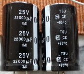
How about a CRCRC filter using these two caps (attached) for the first two caps and a 2200uF for the third? Resistors, I have the choise between 0.1R/5W and 0.22R/5W, that I recall without looking through my parts.
PS being a 19Vdc 3A smps laptop supply.
How about a CRCRC filter using these two caps (attached) for the first two caps and a 2200uF for the third? Resistors, I have the choise between 0.1R/5W and 0.22R/5W, that I recall without looking through my parts.
PS being a 19Vdc 3A smps laptop supply.
Attachments
That would work as I use 2200uF and 0.47R CRCRC and it works well. Put the R on both positive and gnd sides as noise sneaks in on ground side as well.
That would work as I use 2200uF and 0.47R CRCRC and it works well. Put the R on both positive and gnd sides as noise sneaks in on ground side as well.
Thanks, I actually didn't think about the gnd side needing resistors as well.
I tried editing my previous post, but couldn't.
Anyway, will an smps supply be ok with that much capacitance? With the caps I have in mind the total will be 46200uF. Very much overkill but I have the capacitors and I have not found any other use for them (intended as parts to modify a Marantz CD-player with tda1541a.
I have since then gone over to HDD based source).
That's why I use a cap multiplier between SMPS and caps: to slowly ramp current up and not cause SMPS shutdown. I use Juma's design - just 1 n channel MOSFET and 8 passive parts.
Juma's Easy-Peasy Capacitance Multiplier
Juma's Easy-Peasy Capacitance Multiplier
Do you use the 4700uF in the handdrawn schematic, or do you connect the first cap of the filter there?That's why I use a cap multiplier between SMPS and caps: to slowly ramp current up and not cause SMPS shutdown. I use Juma's design - just 1 n channel MOSFET and 8 passive parts.
Juma's Easy-Peasy Capacitance Multiplier
The first cap of the filter replaces the 4700uF. But if you are connecting straight to an amp without a filter keep it. Note that cap Mx will have circa 3-4v dropout so size SMPS upstream voltage appropriately. A 24v SMPS conveniently makes 20v which is a nice voltage to work with. If you want some other value use a DC-DC step up/down converter in between the SMPS and the Cap Mx and you have voltage regulation to any voltage you want. Input can even be a 5v USB power pack.
These are good for about 300mA:
DC-DC Adjustable Step-up boost Power Converter Module XL6009 Replace LM2577 | eBay
These are good for several amps (I have tested to 4amps continuous in Class A):
Adjustable Dc/dc 15a Buck 4-32v 12v to 1.2-32v 5v Converter Step Down Module DMI | eBay
These are good for about 300mA:
DC-DC Adjustable Step-up boost Power Converter Module XL6009 Replace LM2577 | eBay
These are good for several amps (I have tested to 4amps continuous in Class A):
Adjustable Dc/dc 15a Buck 4-32v 12v to 1.2-32v 5v Converter Step Down Module DMI | eBay
Last edited:
Physical issues? Are you making fun of the physical problems I have and have shared in a few posts on this forum?
That would be a very low thing to do.
Nope...I'm not even aware of any "physical issues or problems" you may have. How would I know of any of your "physical issues"??
In this day and time, it seems we ALL have some sort of physical or psychological issues.
I was only asking for a schematic for YOUR version of a AD797/BUF634 amplifier.
Nothing more...nothing less.
If that's too much trouble, then just merely forget it.🙂
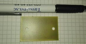
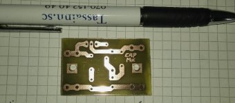
I made a quick layout for the capmx
I figured I'd use the alu enclosure as heatsink for the mosfet.
And yes, I really could use a drillpress as M3 and above without using a centerpunch is not my thing as seen in the pics.
I figured I'd use the alu enclosure as heatsink for the mosfet.
And yes, I really could use a drillpress as M3 and above without using a centerpunch is not my thing as seen in the pics.
Attachments

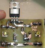
I generally make these with P2P (all secured to the 3 legs of the mosfet as mounted to case). Or veroboard works well too for small IRF610 based ones.
PCB looks good though.
PCB looks good though.
I generally make these with P2P (all secured to the 3 legs of the mosfet as mounted to case). Or veroboard works well too for small IRF610 based ones.
PCB looks good though.
Thanks 🙂
I have plenty of coppper clad boards (70u Cu) and ferric chloride so I kind of do these boards as practice (managed ssop20 so far) until I get my CNC mill/engraver done. And that project is on it's second year...
Having a one year old daughter and 24/7 pain sort of slows everything down to a crawl.
I got the last parts needed (well apart from the 715R, closest I found to 710R) resistor) to finish populating the headamp boards today. Including the 50K ALPS RK27.
Sorry about the OT
Edit: I noticed my mistake using a 100nF where the schematic called for a 1uF, so I soldered a Wima mkt 1uF under the 100nF MKP.
Last edited:
- Home
- Amplifiers
- Headphone Systems
- BF862 based SE Class A Headamp without the HEAT