Not really lol
I like to build stuff, and I have alot of projects going at once.
Some would call that a bad thing as my builds tend to take a while to complete.
I like to build stuff, and I have alot of projects going at once.
Some would call that a bad thing as my builds tend to take a while to complete.
I've gotten a bit more done on this build.
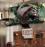
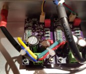
CapMx, CRCRC filter, XMOS to I2S board, CS4397 board, P2P wired LM7812 and some other stuff is mounted in the enclosure. The 7812 is for dropping the +24Vdc to more managable +12Vdc for the two LT1963 that supplies analog and digital supplies to the CS4397.
Still a few things left to do, but I'm slowly getting there.
Edit: the "gunk" is clear, non-conductive silicone glue.
Attachments

Last edited:
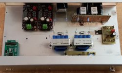
All wiring apart from PS wiring is temporarily done. For the headamp part of the project.
I'll shorten some wires and solder in some when I've tested that everything works. Cable to and from the ALPS is four lead shielded cable with shield connected in one end (to gnd).
Question: I know the bcl clone and ad797/buf634 headamp works as preamp, would this design be able to drive two 20Kohm loads in parallel?
Attachments
Driving two 20k loads is nothing. I use my pocket SE Class A amp as a preamp on my main speaker system. This particular amp should be able to drive 30ohm loads so 20k or 10k is nothing.
Driving two 20k loads is nothing. I use my pocket SE Class A amp as a preamp on my main speaker system. This particular amp should be able to drive 30ohm loads so 20k or 10k is nothing.
I figured that it would be a simple task it.
Not familiar with this type of topology so I thought best to ask.
Thanks 🙂
Getting close to first power on of this project.
I seem to have misplaced all my fuses when moving workspace, I've found two of a couple of hundred. The ones I found are both fast blow, one is 100mA, the other 400mA. I'll put the fuse straight at the 24Vdc in, before the capacitance multiplier. Will any of the two work until I find my collection of fuses? I guess I can rule out the 100mA right away.
I seem to have misplaced all my fuses when moving workspace, I've found two of a couple of hundred. The ones I found are both fast blow, one is 100mA, the other 400mA. I'll put the fuse straight at the 24Vdc in, before the capacitance multiplier. Will any of the two work until I find my collection of fuses? I guess I can rule out the 100mA right away.
Found a few more:
125mA slow
200mA fast
250mA fast
315mA both slow and fast
750mA fast
800mA slow
I found a few more, these are the ones I think may work.
If it were only the headamp and CS4397 I could calculate the value to use, but I don't know the CapMx (the current it draws on it's own) and I need to account for the two LT1963 and the 7812 as well as the CapMx.
Well, I got around to flipping the switch just now.
0.75A fast fuse was ok, the lower values blew very fast.
I measured Vdc at the PS input of the headamp boards, that slowly rose to about 1.5Vdc. At the input of the CapMx I got slightly under 6Vdc. Figured the 24Vdc SMPS was a dud, but without load I got 25Vdc on that. It's only 1A though, could that be the problem?
I also measured at PS in on the CS4397 board (PS chain for that goes: 24Vdc - 7812 - LT1963 - DAC.
I am supposed to get 5Vdc there, I didn't reach 1Vdc.
I am using the 7812 as the max v-in of the LT1963 is 20Vdc. So, do i have an error somewhere or is the SMPS just not up to the task?
I found my error.
Next question, the supply voltage for the headamp boards climbs above 20Vdc. At 20.15Vdc I power off as I am unsure about the max voltage for the jfets.
Next question, the supply voltage for the headamp boards climbs above 20Vdc. At 20.15Vdc I power off as I am unsure about the max voltage for the jfets.
JFETs are rated 20v, but they are not exposed to full rail. I think they are seeing about half Vcc or 10v. So you should be fine. I ran mine at 20v Vcc so you should be good. But 20v will dissipate a lot of heat so in long run maybe aim for 18v.
Last edited:
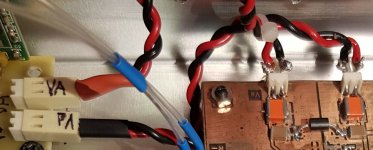
I'm driving the headamp from a CS4397 DAC via a pair of Edcor WSM 600:2K4. I got the advice to hook the pot up between the secondaries of the Edcor WSM's and the headamp boards.
I've got a vcc to the headamp of 19.58Vdc now, using drop resistors on the pos leads from the CRCRC filter to the headamp.
Vcc levels out at about 19.58Vdc as I wrote, but with the volume all the way down I get terrible DC-offset. Turning the pot up lowers the DC-offset to acceptable levels.
This leads me to think I don't have the pot properly installed. In is hooked up to pos secondary, gnd is hooked up to neg secondary. Out goes to +in and gnd to input gnd.
I may well have misunderstood the advice I was given as, I think, turning the pot (being "across" the secondaries) alters the termination of the transformer. There's a resistor there to terminate the transformer, won't the pot act as a parallel variable resistor?
If I put the pot after the headamp...that doesn't seem right either.
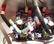
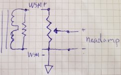
A pic speaks a thousand words?
Ithink I got the drawing right.
I have connected the gnd pins on the pot together, mistake?
The resistance across the secondaries should stay the same, in this case 50K in parallel with the terminating resistor.
It seem that unloaded, the headamp doesn't like it's input shorted to gnd? That is more or less the result of the pot turned all the way down.
Well, gnd and neg secondary as it's wired atm.
Attachments
Nice work. You did a DIY DAC? Very cool. I like xmos USB adapter too. I got this and it works quite well. Has BB PCM5102 DAC. Nowadays I mostly use the Focusrite 2i4 2nd gen as a DAC and that sounds very good too. Capable of high speed rates.
New version Assembled XMOS U8 + PCM5102 + TDA1308 USB Coaxial DAC Sound Card 32bit 384K headphone Output ,Free Shipping-in Amplifier from Consumer Electronics on Aliexpress.com | Alibaba Group
Everything oke with X? I have started again with the amps, busy with a winding machine for small signal transformers, needed for the amps to get a Fase shift transformer.
nice thread here.
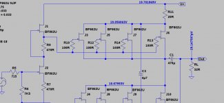
From my simulation only the "bottom half" get about half the vcc.
The others get full/almost full vcc. With reservation for mistakes possibly made in the simulation.
The top half sees around 19.1-10.1=9V according to your simulation so it should be ok.
The top half sees around 19.1-10.1=9V according to your simulation so it should be ok.
That is with the voltage drop resistors. 🙂
That is with the voltage drop resistors. 🙂
Well it is far from VCC anyway
From my simulation only the "bottom half" get about half the vcc.
The others get full/almost full vcc. With reservation for mistakes possibly made in the simulation.
The top is at 19v but their source is at 10v (as can be seen as input to drain of bottom FETs), so net result is only about 9v Vds on top FETs.
So do you have first sound yet?
Last edited:
Everything oke with X? I have started again with the amps, busy with a winding machine for small signal transformers, needed for the amps to get a Fase shift transformer.
nice thread here.
Hi Kees,
All is well here. My latest project is over here:
AKSA's Lender Preamp with 40Vpp Output
Here is the result for 20vpp into 7okhms:
All with just 6 transistors.
- Home
- Amplifiers
- Headphone Systems
- BF862 based SE Class A Headamp without the HEAT