jwb said:
Here's my 9V version of the design by salas. I think it's brilliant.
I was forced to use IRF9610 because I don't have any power P-channel FETs on hand. The 9610 has Rds(on) about six times higher than the IRFP9240, so the line regulation is not as good. But it works! It doesn't oscillate at all, and whatever noise there may be is well below the ability of my scope to measure (also well below the noise from the bench supply input.)
I like it!
jwb,
The RdsOn of the MOSFET is of no significance here, because the FET is not used fully on. It has no impact at all on any of the regulation parameters. It always has the full Vout across it and whatever current is necessary to maintain the output at the set value.
Jan Didden
There's an interesting audioXpress article on this subject:
http://www.borbelyaudio.com/pics/waagbo2863.pdf
http://www.borbelyaudio.com/pics/waagbo2863.pdf
ikoflexer said:franken output impedance.
ikoflexer,
What ESR and ESL values are you using for the OP capacitor
model on these sims?
T
jwb said:
Here's my 9V version of the design by salas. I think it's brilliant.
I was forced to use IRF9610 because I don't have any power P-channel FETs on hand. The 9610 has Rds(on) about six times higher than the IRFP9240, so the line regulation is not as good. But it works! It doesn't oscillate at all, and whatever noise there may be is well below the ability of my scope to measure (also well below the noise from the bench supply input.)
I like it!
Yes its great for noise. It had proved it many times. As I see, you made it with a Vbe controlled CCS since I don't see any LEDS, and used CCS instead of R6. Good news it will not oscillate even with the CL, OLG ratio having been dynamically changed, and much faster Mosfets. I will mod it in the next few hours and listen. Lower Rds(on) Mosfets always give me better bass. That is why I use them, I have compared.
I don't know how you measured pinch off voltage Vp, but 0.2Vp for Idss~10mA device cannot be right. Look at the graphs. 10mA must be >0.6Vp.
I just measured a 10.2mA Idss LSK170
Vp=0.68V for Id~1uA
Vp=0.695V for Id~0.3uA
This requires ~ 2 * 0.69 + 0.1 >1.48V from the cascode to get the CCS to operate properly and meet Jung's criteria.
Even a darlington for the BC cannot achieve that.
I just measured a 10.2mA Idss LSK170
Vp=0.68V for Id~1uA
Vp=0.695V for Id~0.3uA
This requires ~ 2 * 0.69 + 0.1 >1.48V from the cascode to get the CCS to operate properly and meet Jung's criteria.
Even a darlington for the BC cannot achieve that.
I just measured 0.6475V Vbe in a working example and the JFET still pulls IDSS Vdrop on its tale to ground 10R resistor. So the particular one it can't be over 0.65V Vp. What IDSS you recommend so to statistically stay away from surprises when we choose the Zener tail JFET?
AndrewT said:I don't know how you measured pinch off voltage Vp, but 0.2Vp for Idss~10mA device cannot be right. Look at the graphs. 10mA must be >0.6Vp.
I just measured a 10.2mA Idss LSK170
Vp=0.68V for Id~1uA
Vp=0.695V for Id~0.3uA
This requires ~ 2 * 0.69 + 0.1 >1.48V from the cascode to get the CCS to operate properly and meet Jung's criteria.
Even a darlington for the BC cannot achieve that.
For a N channel JFET, Vp is always negative. Don't know what you measured?
All points on the Id=f(Vgs) with Vgs=Vds (it's a parable) are called "incipient saturation". For each of these points, keep the Vgs and add a |Vp| to Vds. This is "saturation" in Walt's sense.
Example: A LSK170 has Vp=-0.6V and Idss=10mA, that is, at Vgs=Vds=0, Id=10mA. Therefore, at Vgs=0V and Vds=0+|-0.6V|=0.6V the LSK170 is in saturation.
In contrast, the region where Vds<Vgs is called "linear region" and the JFET is essentially a voltage controlled resistor.
Janneman and syn08, thanks for your suggestions. Jwb has good news, it won't oscillate! I will mod it and tell you the subjective stuff. Thanks again!
Terry Demol said:
ikoflexer,
What ESR and ESL values are you using for the OP capacitor
model on these sims?
T
Used .5 ohms ESR for all caps in the simulation, and no ESL. What value would you recommend I use for ESL? Thanks.
Edit: BTW, here's another result using the lm4562.
Attachments
Guys, a philosophical question:
Given I have very low noise from the shunt, shall I improve ripple before the shunt with CRC so to help its not stellar regulation passively, without further real circuit manipulations? Because even with the resistive BJT load original I haven't got significant ripple even in 60dB gain phono stages in practice. Given the large rectification caps before the shunt and the local RC filters on the phono.
Given I have very low noise from the shunt, shall I improve ripple before the shunt with CRC so to help its not stellar regulation passively, without further real circuit manipulations? Because even with the resistive BJT load original I haven't got significant ripple even in 60dB gain phono stages in practice. Given the large rectification caps before the shunt and the local RC filters on the phono.
salas said:[snip]Lower Rds(on) Mosfets always give me better bass. That is why I use them, I have compared.
Yeah sure.😉
Jan Didden
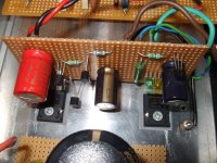
Jan, I replaced the R6 1k load with your recommended Idss Njfet CCS load. I does not oscillate, it worked OK for a series of on/off cycles loaded by 2 channels phono stage, 40mA total for about an hour. Here is a picture, you can see a 7.8mA Idss 2SK170BL in place of R6. (The one with the 2 grouped legs). Thank you!
I am about to listen to it carefully now and report in a while. 😉 Silly me or not, if I can't tell a positive difference by ear, I don't adopt stuff. I maintain that the only goal in making audio devices is better listening in the way or method anybody thinks is suitable no matter how flawed. Yes, low Rds (on) hefty Mosfets sound more substantial to me in the shunt, I took time to try out some alternatives. I know I must amuse real engineers, you gave me a tip, I gotta pay back with some comedy at least!
I also took an FFT of the phono + modded shunt. Not much better noise floor under 1kHz, a bit smoother there, 3-5dB lowering of my hum spikes but better noise floor in the highs. The FFT is presented in 1/24 octave, not exponential.
Attachments
salas said:The FFT. This comes from my 44dB phono version, driven with 1mV 1kHz. Both channels are fed by the modded shunt reg above. 1/24 octave scaling for X axis, 0dbV = 1V RMS for Y axis. Emu Tracker Pre at 48kHz sampling rate, 24 bit.
You've got some issues there...
Yes I have a mains transformer and 230VAC cable at about 15cm away from the Riaa and about 10cm away from the shunt, in the same box. So I get some mains 50Hz hum and its harmonics summing etc. But I have measured very expensive commercial phono stages in huge boxes and they give the same stuff plus 100Hz at around -80dB, so I think I must be content. My box is 26cm wide.
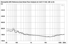
Audio Research Reference Phono model's noise floor (lowest gain, shorted inputs, looks like exponential X axis). Stereophile Year 2000 model measured.
Audio Research Reference Phono model's noise floor (lowest gain, shorted inputs, looks like exponential X axis). Stereophile Year 2000 model measured.
Attachments
salas said:
Yes its great for noise. It had proved it many times. As I see, you made it with a Vbe controlled CCS since I don't see any LEDS
I used a Zener for this, not having enough LEDs on hand.
and used CCS instead of R6.
Not sure which one was R6? Your last schematic has no R6....
Sound Check
OK I have listened to the added CCS mod carefully with known material:
The shunt + phono is a little softer in the highs and a little broader in the mids now. It gives a slightly better ''together'' feel including the bass. It may have lost some U shape depth of imaging, I have to listen more to confirm that. Perceptible differences but not high contrast ones, rather positive, to conclude for now. I will wait to hear the opinion of a couple of friends that will do the mod and listen independently in their systems. If it proves positive overall, I will recommend the mod to the gang that made my phono and shunt in the respective thread.
I would like to thank again Jan and syn08 for the tip, analysis and cautions. Also for putting up humorously with my subjective bubble talks. Also jwb for making it and confirming its low noise (top priority when using it for phono), Ikoflexer for his rapid simulations and support, as well as all the good people sharing their ideas and knowledge in this thread. Last but not least, analog sa for opening this thread. I don't know for best low noise reg, but what I got is low noise at least and suits my purposes. So I am content. Thanx fellas!
salas said:The 1k load on the BC550C collector, before the suggestion to put a Jfet CCS there. See in the schematic under the noise comparison scope picture post.
Ah yes, I did use the active load there. 2SK170, just like your drawing. It seems to me that the added gain is helpful.
salas said:
Audio Research Reference Phono model's noise floor (lowest gain, shorted inputs, looks like exponential X axis). Stereophile Year 2000 model measured.
Which issue of Stereophile was that from ? -- the noised is referenced below 5mV? I think they are just measuring amplitude with the inputs shorted.
If you want to measure noise of an amplifier without the benefit of a sharp bandpass filter, measure with a 1K resistor then a 10K resistor, then short the inputs. You should be able to derive the device noise, separated from the ambient under these conditions.
- Home
- Amplifiers
- Power Supplies
- Best low noise regulator?