keantoken said:
http://www.diyaudio.com/forums/showthread.php?postid=1759105#post1759105
The 2N6387 is a power darlington! Is this an error?
- keantoken
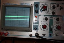
It is indeed a power darlington. And in that circuit it gave me the best performance, in reality, as you see the attached scope pic, of the regulator output when attached to the phono preamp, sadly just a prototype without a good layout, etc. There is room for improvement. Lower trace is the scope channel on its GND setting (thinnest trace possible), upper trace is the regulator, scope on 5mV/div. I expect even better results from a Jung regulator.
I will get back with more comments about the rest a bit later.
Attachments
I would see about TIP110 too, which gives higher hfe when the current is lower. 6387 is at its best when the currents are very strong.
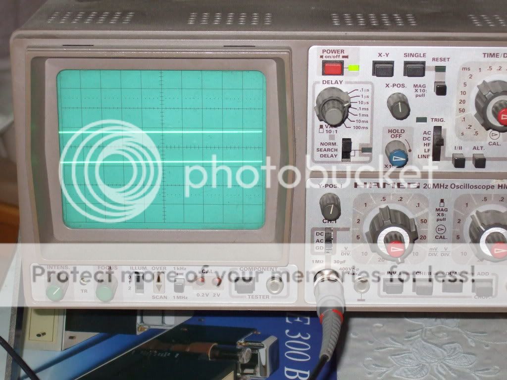
Out of curiosity, I run your test too, setting my scope on dual channel 5mV/div. Channel one is the output of my standard LED MOSFET CCS shunt @ 200mA when feeding my NJFET phono (upper trace). Lower trace is channel two, just on scope's own GND. I don't see any difference in thickness or any fuzziness. Maybe you pick up some spurious noise?
An externally hosted image should be here but it was not working when we last tested it.
Attachments
salas, that looks very nice; I have yet to get such a clean trace from any of the regulators I built, including the schematic you have shown.
Getting a visually much thicker and fuzzier line even with your ''turbo'' version is suspect IMHO. Points to some grounding issue or noise pick up possibly. In page one there are some analogous scope pics from a CRC pre filtered Jung in a Marantz. It thickens there too when applied to the machine. Environmental noise or total loop gnd issues again maybe.
salas said:Getting a visually much thicker and fuzzier line even with your ''turbo'' version is suspect IMHO. Points to some grounding issue or noise pick up possibly. In page one there are some analogous scope pics from a CRC pre filtered Jung in a Marantz. It thickens there too when applied to the machine. Environmental noise or total loop gnd issues again maybe.
I noticed that too, and I agree with you. This probably points to the fact that if the implementation is done well (grounding and all else) this discussion about the different regulators becomes very much just academic.
As far as academic discussions go, simulating with the TIP110 does indeed improve performance a bit. I'll look for a tip110 to try in the real circuit and see what happens.
Thanks for the tip (no pun intended) 🙂 I don't know about others, but I've learned to appreciate the quality of your advice.
The scope is helpful when you measure noise -- better yet, it is helpful to have an "envelope" function -- so you can see what's going on over time. You have to baseline everything. Texas Instruments has a nice circuit for measuring regulator noise -- it's on the product folder for the TL431 regulator.
Almost all "True RMS" meters I measured for an AX article fall down when measuring noise -- except the Hewlett Packard 3403C or the Fluke 8620A -- the latter is usually on EBay for the price of a decent Cote du Rhone. Folks reported back to me that the older HP's, GenRad's and Boonton's worked well too. The true RMS converters from Linear Tech are almost as good as the HP and Fluke meters cited above.
I will stick with the Jung/Didden -- Jan's testing of the noise and impedance was well documented -- while WJ certainly had a expressed fondness for the AD797, I have used the AD825 and various Linear Tech devices and the performance is only slightly inferior to the AD797.
Giasou Salas,
I like your shuntreg from post #103 but one thing is not entirely clear to me: you bias JFETs (Q2 and Q5) at Idss and you use R5 (100 R) and R3 (10 R) just to lift JFETs a bit from the ground. What is it good for (using R3 and R5 like this)?
Thanks
I like your shuntreg from post #103 but one thing is not entirely clear to me: you bias JFETs (Q2 and Q5) at Idss and you use R5 (100 R) and R3 (10 R) just to lift JFETs a bit from the ground. What is it good for (using R3 and R5 like this)?
Thanks
Gave me quicker transient response in this particular implementation.
How is your current mirror one doing? Still on LM317 CCS?
How is your current mirror one doing? Still on LM317 CCS?
salas said:Gave me quicker transient response in this particular implementation.
How is your current mirror one doing? Still on LM317 CCS?
On the scope I can't see the difference - it looks the same with LM317 as CCS but with MOSFET/LED CCS there is a certain positive quality of sound in highs, so I'll stick with it 😉
Its difficult to ''see'' subjective impacts between very well performing regulators just by modeling or measurement. Most are technically more than adequate for their main mission. But if not actually implemented and subjectively tested they can't really be selected. Of course this will sound weird to all engineers, but what can I say more? Its my practical experience or illusion 🙂 . I have promised you better highs with the LED Mosfet CCS, remember? Those subjective things magnify if in phono circuits. Yours is line if I remember correctly?
P.S. That 27V/1W over the zener in the circuit under the scope pic is a typo. Its actually a 24V Zener, and its part number is correct. It can be made for different voltages by changing the Zener and feeding about 7-8V more Vin than Vout. The limit is about 43V DC Vin due to the 40V max of the 2SK170 on the left. I change that to a ring of two higher voltage pair if I wanna go higher. I use about 10mA Idss or I set the ring of two at 10mA so to help the LEDS work at their good region. Red or green under 2V ones are most adequate.
P.S. That 27V/1W over the zener in the circuit under the scope pic is a typo. Its actually a 24V Zener, and its part number is correct. It can be made for different voltages by changing the Zener and feeding about 7-8V more Vin than Vout. The limit is about 43V DC Vin due to the 40V max of the 2SK170 on the left. I change that to a ring of two higher voltage pair if I wanna go higher. I use about 10mA Idss or I set the ring of two at 10mA so to help the LEDS work at their good region. Red or green under 2V ones are most adequate.
Of course, I had previously experienced what you say so it's no surprise to me, but you have to admit that when you need a quick check of the circuit it's so tempting to use LM317 - it's so simple 😀
Naturally, we are now talking nuances and tastes are different, but it is undeniable that difference in sound exists.
Naturally, we are now talking nuances and tastes are different, but it is undeniable that difference in sound exists.
I admit!😀 But I am happy also that you did not stay to the quick solution and you tested the properly advised one. Good listening.
Only thing that worries me is Pd of Q2 - with 10mA Id Pd is more than 250 mW 
It might be solved by using the R5 of higher value - like 1K maybe ?
Otherwise
It might be solved by using the R5 of higher value - like 1K maybe ?
Otherwise
Salas,
I'm not sure I understand your shunt reg. How much current is there going through the zener? And where is that current going to?
Jan Didden
I'm not sure I understand your shunt reg. How much current is there going through the zener? And where is that current going to?
Jan Didden
juma said:Only thing that worries me is Pd of Q2 - with 10mA Id Pd is more than 250 mW
It might be solved by using the R5 of higher value - like 1K maybe ?
Otherwise
Its a 400mW part and none have failed in 5 months 24/7 power on. So no worries.
No that's not my point. How much current does it run, and where is that current going to? Into the base or into the current source?
Jan Didden
Jan Didden
janneman said:No that's not my point. How much current does it run, and where is that current going to? Into the base or into the current source?
Jan Didden
Sorry, that was going to Juma, but you posted in meantime.
Q5's almost Idss current runs through the Zener. Its not going to the BC550C's base.
- Home
- Amplifiers
- Power Supplies
- Best low noise regulator?