Thanks Julf differential inputs of opamps have been misused for a long time as balanced line receivers and mixers. The circuit above is doing it correctly.
Can you educate us by explaining why you think using the differential inputs of an opamp is incorrect? After all, if you look at what is inside the opamp, you basically find a 5-transistor version of the input stages of your circuit.
seeing those large input caps so the topology still has some polishing to do by probably adding one or more opamps to tweak the topology to work with 10uf or lower,
I have no idea what that means. Is this from a parallel universe? 😎
Jan
I have no idea what that means. Is this from a parallel universe? 😎
Hoping OnAudio can explain how he calculated/determined the values of those capacitors (and how he thinks extra opamps help reduce their values)...
Differential opamp inputs work great for feedback where they should be used
Can you educate us by explaining why you think using the differential inputs of an opamp is incorrect? After all, if you look at what is inside the opamp, you basically find a 5-transistor version of the input stages of your circuit.
From a purist perspective 😉
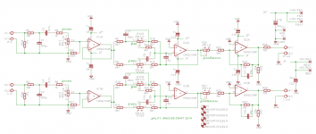
If you own some Elac debut 2.0 b6.2 or Buchardt s400 speakers a preamp like P1 would work well. Note on the grail of simplicity unnecessary caps and switches are avoided, there’s no tone defeat, no high level inputs, you either use the circuit or not at all. This circuit also allows you to use mono blocks
If you own some Elac debut 2.0 b6.2 or Buchardt s400 speakers a preamp like P1 would work well. Note on the grail of simplicity unnecessary caps and switches are avoided, there’s no tone defeat, no high level inputs, you either use the circuit or not at all. This circuit also allows you to use mono blocks
I have no idea what that means. Is this from a parallel universe? 😎
Jan
Attachments
Last edited:
From a purist perspective 😉
So the purist perspective is to keep adding more redundant opamps in the signal path? 🙂
Differential opamp inputs work great for feedback where they should be used
"Why shouldn't you store beer in the fridge?" "Because a fridge works great for storing food". Yes, sure, but... let me repeat my question that you didn't answer:
Can you educate us by explaining why you think using the differential inputs of an opamp is incorrect? After all, if you look at what is inside the opamp, you basically find a 5-transistor version of the input stages of your circuit.
A sim and short explanation will come in handy
"Why shouldn't you store beer in the fridge?" "Because a fridge works great for storing food". Yes, sure, but... let me repeat my question that you didn't answer:
Can you educate us by explaining why you think using the differential inputs of an opamp is incorrect? After all, if you look at what is inside the opamp, you basically find a 5-transistor version of the input stages of your circuit.
So the purist perspective is to keep adding more redundant opamps in the signal path? 🙂
... and still with an input coupling cap.
Fake news in audio, who would have thunk!
Jan
I'm doing a version of this myself, based on PGA2310. Original plan was to reuse pseudo-floating stages of DCX2496 but your suggestion regarding shortest possible path got me thinking, maybe I could get away with impedance balanced (matched resistors on hot and cold wires) output. After all if I'm going to use balanced interconnects, it's not pro environment with 100m cablesOK, sorry not to be clear. I only suggested to connect the wires you put in at another point, thus saving a couple of ICs in the signal path. No other changes than you did.
But if you don't mind the extra ICs, that's fine of course.
When I did my own extensive mod with the remote vol/bal control for the DCX2496, I realized that shortest signal path is important for best results.
Jan
A sim and short explanation will come in handy
So, in a shorty and sim (sic) summary, no, you can't.
Thanks Jan, ease up man😀, there are many levels of purism from the B1 buffer, its revisions and clones simply providing low impedance output after a volume control using a jfet or bjt with caps and without to the now Korg triode, Pass does a good job 😉
But then there be mongrels like P1, but is it the best of the worlds ? You decide
Julf, sorry to keep you waiting, will now introduce old new style, lets assume two errors (theoretical), one an inversion of the other come in from the balanced source, what happens next ?
If above holds then we should be able to get better measurements or better sounding experience
How important is it ? You decide
Julf, sorry to keep you waiting, will now introduce old new style, lets assume two errors (theoretical), one an inversion of the other come in from the balanced source, what happens next ?
If the error is differential (one an inversion of the other) and comes from the source, it is totally indistinguishable from the actual signal, no matter what your circuitry. Differential/balanced only helps against common mode noise/error.
Don't confuse him with facts/figures 😎
Indeed. I just realized from his answer in another thread that he has fundamental misunderstandings about how electricity works.
Hello there,
how can i reach these values with my DCX2496?
Low-pass: 2nd order, fc=300Hz, Q=0.4
You have to program a LP Butt 13 @303Hz
and an eq : -4.9dB 303Hz 0.71 parametric
High-pass: 2nd order, fc=350Hz, Q=0.67
HP Butt12 352Hz and eq : -0.5dB 352Hz 0.71 parametric
...If above holds then we should be able to get better measurements...
Ho, ho, ho, ho.... at last OnAudio is going to show us some measurements.
Or did you mean that even though you've never seen any meaningful measurements depicting the many hypothesized audible flaws of the stock DCX2496, you were absolutely certain that somebody* someday would post some measurements eventually?
B.
* except for those selling fix-it kits
Last edited:
Ho, ho, ho, ho.... at last OnAudio is going to show us some measurements.
🙂
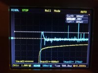
Guys, I'm in desperation. Trying to troubleshoot turn-off thump. Tracked it down to -15V rail going positive (!) briefly after shutdown, which in turn causes opamps to go crazy. This seems to be PSU related as it happens even with DCX mainboard disconnected. I've checked all caps, diodes etc. The only thing I haven't tried replacing are the regulators themselves. Putting Schottky diodes across rails (as per schematic) helps in that the bump is decreased but is still present. The bump increases with capacity before regulators, so it seems something is discharging very inappropriately.
Attached is a screenshot from my scope, yellow trace is voltage before regulator, blue - after. This is with 100uF caps before regulators so the bump is relatively small.
Also included the relevant portion of PSU schematic for reference.
Any ideas would be greatly appreciated!
Attached is a screenshot from my scope, yellow trace is voltage before regulator, blue - after. This is with 100uF caps before regulators so the bump is relatively small.
Also included the relevant portion of PSU schematic for reference.
Any ideas would be greatly appreciated!
Attachments

But isn't there a mute function in the DCX that shorts the output when switching on/off? Was that disabled?
Unlikely that replacing caps and diodes will change it, it's an interplay of supply rate of rise and the load currents required by the various circuits. The only sure way is a mute circuit.
Jan
Unlikely that replacing caps and diodes will change it, it's an interplay of supply rate of rise and the load currents required by the various circuits. The only sure way is a mute circuit.
Jan
- Home
- Source & Line
- Digital Line Level
- Behringer DCX2496 digital X-over