Good stuff!
Say, did you manage to get a refund on your ebay fet order?
Sadly no, but they at least seems legit, I'll try to test them (It will let me learn how to match fets) after this project.
I'm finishing the 3D work on my enclosure, I'll post renders later today. I have to convert them to dxf cad files for laser cutting.
Nice job.
Are you going to mount it with the boards together or split them up? They just snap apart, and you can spread the heat a bit. Either way, be sure to connect the output boards to the appropriate headers on the main board.
Are you going to mount it with the boards together or split them up? They just snap apart, and you can spread the heat a bit. Either way, be sure to connect the output boards to the appropriate headers on the main board.
Bob brought up a good point. I recommend splitting the boards so that
power mosfets can be mounted horizontally on the heatsink, at a little
less than half the height of the heatsink.
power mosfets can be mounted horizontally on the heatsink, at a little
less than half the height of the heatsink.
Of course, I'll detach the header boards, I just left them attached to facilitate the soldering and handling process.
The header boards will be mounted horizontally at nearly 1/3 bottom of the heatsinks, You will see my populating project with the 3D images I'll post in a moment. I wait for your comments on it 🙂
The header boards will be mounted horizontally at nearly 1/3 bottom of the heatsinks, You will see my populating project with the 3D images I'll post in a moment. I wait for your comments on it 🙂
It's probably a little easier to split them first, but find a sharp corner that will fit between soldered parts to snap them on. The scoring helps but I remember it took a fair amount of force to snap my boards.
Here some picture of my future Enclosure, those are mainly 3dsmax viewport screenshots, I do not have made any lighting and rendering rig yet.
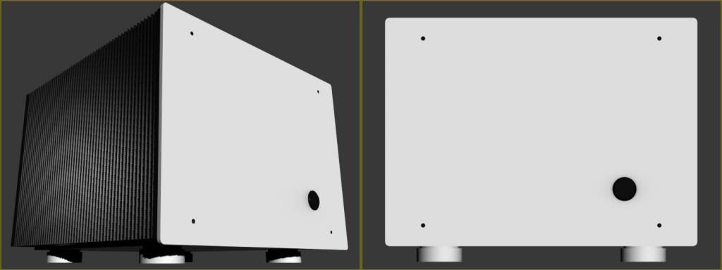
Front perspective and front.
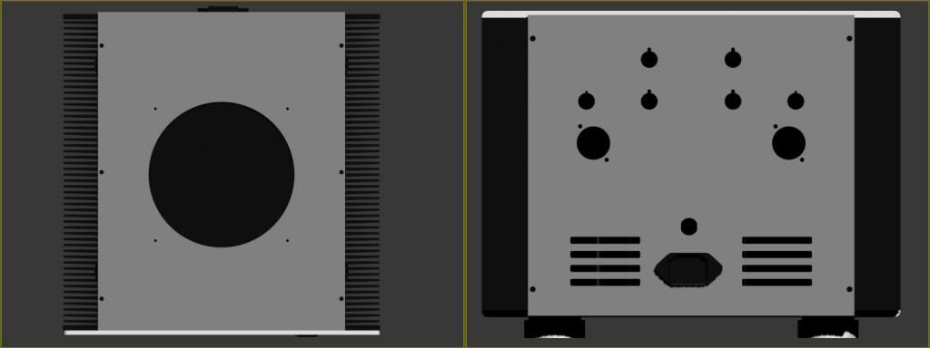
Top and rear.

Rear and top perspective

Inside arrangement (notice the cylinder on top witch symbolize the fan)
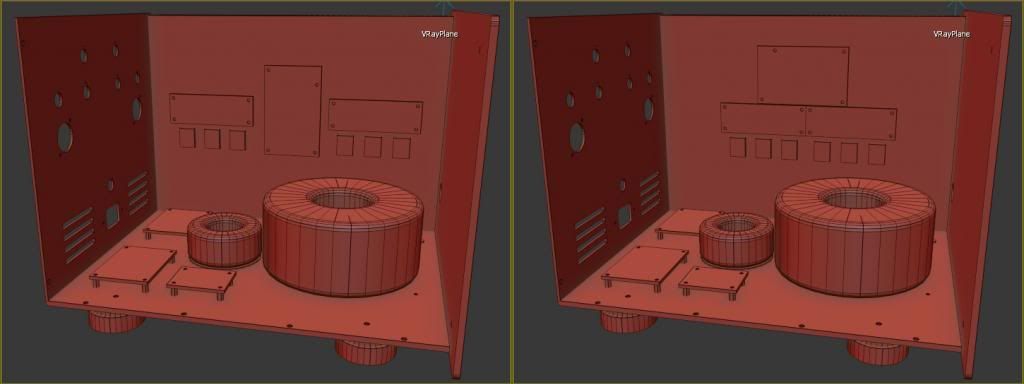
Two different arrangement for amp boards and fets, witch one do you think is the best?
Any comments are welcome!

Front perspective and front.

Top and rear.

Rear and top perspective

Inside arrangement (notice the cylinder on top witch symbolize the fan)

Two different arrangement for amp boards and fets, witch one do you think is the best?
Any comments are welcome!
Oh my....what beautiful work.
I suspect you can get more from the heatsinks by separating the two banks
of mosfets a bit in the second arrangement.
I suspect you can get more from the heatsinks by separating the two banks
of mosfets a bit in the second arrangement.
Does the first arrangement center each bank of mosfets in its half of the sink? That's where I'd go.
air intake holes in bottom plate
please
with cherry on top
😉
No problem for a little drink 😉, maybe a little Pedro Ximénez with a bite of chocolate

Speaking of air intake hole, you're speaking about the rectangle holes on the rear plate right?
in fact, I wanted to set the fan in blowing mode (taking outside fresh air inside the chassis), do you think extracting should be better?
no need for fan messing with temp equilibrium of parts inside , if heatsinks are up to task and you have enough holes for unforced ventilation
remember that output offset and iq are maintained with temp. equilibrium conditions ; inducing fan , if you really don't need it, is counterproductive
remember that output offset and iq are maintained with temp. equilibrium conditions ; inducing fan , if you really don't need it, is counterproductive
I'm quite lost, since it seems that my heatsinks are a little on the weak size (300x210x40 with 32VDC rails) for my project, BobEllis suggested to use a fan to cope with the heat (I choose a 140mm fan at max 1000rpm).
Shall I forget about the fan and risk an overheat?
Shall I forget about the fan and risk an overheat?

Sufficient?

if everything is up to scale and I'm judging by it's looks by experience , I believe your heatsinks are good up to some 120-130W of dissipation per channel
if you aren't comfortable with temp at preferred Iq , make Babysitter - one lazy 12cm fan per side
regarding holes - you need at least 8 times more then you drew , same size on bottom and top plate
blowing air through inside will not help much , regarding heatsink temp , fins are outside

look here for proper ventilation example :
http://www.zenmod.in.rs/my-people/papas-koan-m2-an-amp-for-living-room/
Last edited:
Well, I don't really know anymore what I should choose between air cooling (I already have the 140mm fan and fan controler) or passive cooling with airholes
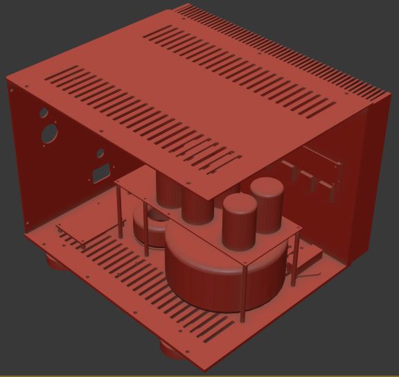
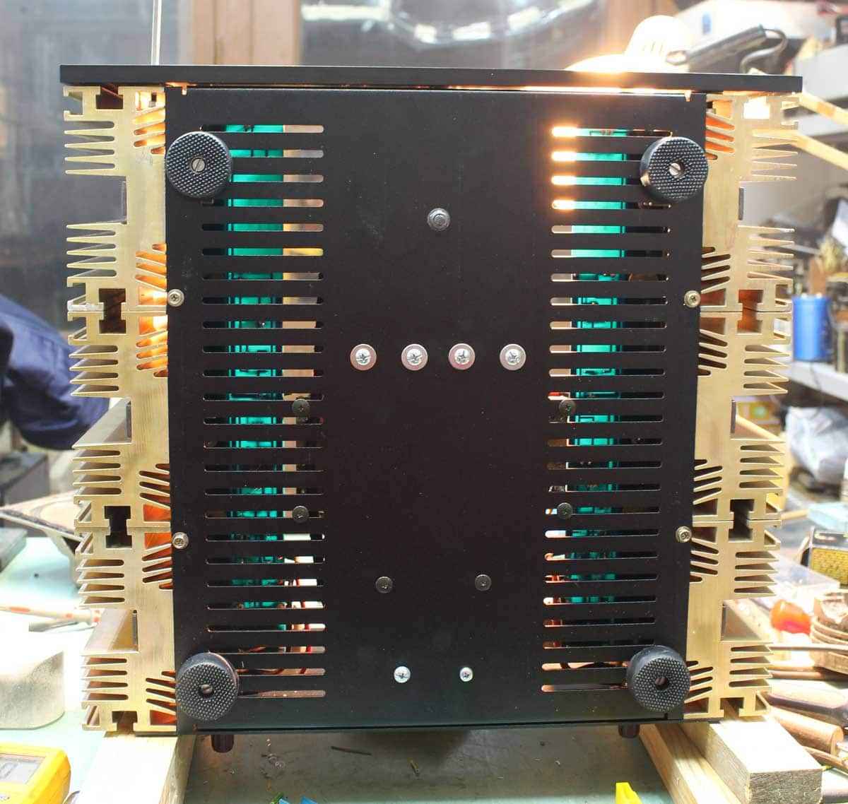
My passive airholes proposal
I have to look for the price of the cut witch will be quite high with that much airholes (a total of 100)
I saw with the spreadsheet that with a bias of 2A (41W under 8R) I can expect 128W of dissipation per channels, how do I set the bias on the boards?

My passive airholes proposal
I have to look for the price of the cut witch will be quite high with that much airholes (a total of 100)
I saw with the spreadsheet that with a bias of 2A (41W under 8R) I can expect 128W of dissipation per channels, how do I set the bias on the boards?
Last edited:
- Status
- Not open for further replies.
- Home
- Amplifiers
- Pass Labs
- Beginner to build an Aleph30 needs some help