Hello everybody!
As promised, Here's the first step of my Aleph amp WIP:
THE PSU.
To begin, here a picture of all the parts used for the building.
The tools:
Regulated Solder iron (set at 330C°)
0.5 Sn62PbAg2 solder
De-soldering wick
Precision cutting pliers
Magnifying light
Isopropanol and antistatic wiper (glasses wiper)
Parts (Digikey refs):
D1-D4 MUR1560GOS-ND DIODE ULT FAST 600V 15A TO220AC X4
D1-D4 HS346-ND HEATSINK TO-220 W/PINS 1.5"TALL X4
C3-C8 338-1599-ND CAP ALUM 22000UF 50V 20% SNAP X6
R1,R22 PPC2.2KW-2CT-ND RES 2.2K OHM 2W 5% AXIAL X2
R3-R12 P0.47W-3BK-ND RES 0.47 OHM 3W 5% AXIAL X10
R0-alt PPC10.0KXCT-ND RES 10K OHM 1/2W 1% AXIAL X1
LED 60-1602-ND LED 3MM DUAL FLANGE BLUE CLEAR X1
C0 Nichicon FW 10uf 50V X1
D0 1N4007 diode X1
C1,C2 Wima MKP4 0.1uf 250V X2
Terminal blocks
2ways 7.5mm X2
3ways 5mm X3
M3 Scews & bolts for the diodes X4
M3 Nylon screw isolators X4
Keratherm White insulators X4
The first step was to clean all the contacts and component legs with isopropanol (99% grain alcohol), maybe not necessary for mint component, but will not hurt.
Soldering process starts with the smaller parts (R0, D0), then R1-R2, R3-R12, C1-C2, C0, LED, Terminal posts.
I then soldered the huge C3-C8.
The soldering process is quite straightforward, you just have to make sure to respect the Electrolytics polarity (Films are non polar) as well as the led polarity (the round contact on the PCB is the positive, square negative).
I chosen 10K res for R0 (witch controls LED brightness) because 4.75K was far too bright (thanks for the advice BobEllis)
Now for the diodes on their heatsinks.
The heatsinks where delivered non drilled, there was just an emboss on the surface, but you have to drill it yourself... No big deal, a 3mm drill bit with some cutting oil (useful to protect the drill bits and avoid aluminum shards). A little cleaning with isopropanol (this chemical is incredible) to get rid of any oil remains and good to go.
Before
After
I then trimmed the Keratherm pads a little to match the height of the diodes and mounted them on the heatsink (I ain't added any thermal compound as Kerafol claim that it's not necessary) with nuts/ bolts and nylon canons (screw isolators)
I then finally soldered the diodes on the board, ensuring that their Cathodes where linked to the C3-C8 positive pole.
FINISHED!!! 😀
Now for the tests......
As promised, Here's the first step of my Aleph amp WIP:
THE PSU.
To begin, here a picture of all the parts used for the building.
An externally hosted image should be here but it was not working when we last tested it.
The tools:
Regulated Solder iron (set at 330C°)
0.5 Sn62PbAg2 solder
De-soldering wick
Precision cutting pliers
Magnifying light
Isopropanol and antistatic wiper (glasses wiper)
Parts (Digikey refs):
D1-D4 MUR1560GOS-ND DIODE ULT FAST 600V 15A TO220AC X4
D1-D4 HS346-ND HEATSINK TO-220 W/PINS 1.5"TALL X4
C3-C8 338-1599-ND CAP ALUM 22000UF 50V 20% SNAP X6
R1,R22 PPC2.2KW-2CT-ND RES 2.2K OHM 2W 5% AXIAL X2
R3-R12 P0.47W-3BK-ND RES 0.47 OHM 3W 5% AXIAL X10
R0-alt PPC10.0KXCT-ND RES 10K OHM 1/2W 1% AXIAL X1
LED 60-1602-ND LED 3MM DUAL FLANGE BLUE CLEAR X1
C0 Nichicon FW 10uf 50V X1
D0 1N4007 diode X1
C1,C2 Wima MKP4 0.1uf 250V X2
Terminal blocks
2ways 7.5mm X2
3ways 5mm X3
M3 Scews & bolts for the diodes X4
M3 Nylon screw isolators X4
Keratherm White insulators X4
The first step was to clean all the contacts and component legs with isopropanol (99% grain alcohol), maybe not necessary for mint component, but will not hurt.
An externally hosted image should be here but it was not working when we last tested it.
Soldering process starts with the smaller parts (R0, D0), then R1-R2, R3-R12, C1-C2, C0, LED, Terminal posts.
I then soldered the huge C3-C8.
The soldering process is quite straightforward, you just have to make sure to respect the Electrolytics polarity (Films are non polar) as well as the led polarity (the round contact on the PCB is the positive, square negative).
I chosen 10K res for R0 (witch controls LED brightness) because 4.75K was far too bright (thanks for the advice BobEllis)
Now for the diodes on their heatsinks.
The heatsinks where delivered non drilled, there was just an emboss on the surface, but you have to drill it yourself... No big deal, a 3mm drill bit with some cutting oil (useful to protect the drill bits and avoid aluminum shards). A little cleaning with isopropanol (this chemical is incredible) to get rid of any oil remains and good to go.
An externally hosted image should be here but it was not working when we last tested it.
Before
An externally hosted image should be here but it was not working when we last tested it.
After
I then trimmed the Keratherm pads a little to match the height of the diodes and mounted them on the heatsink (I ain't added any thermal compound as Kerafol claim that it's not necessary) with nuts/ bolts and nylon canons (screw isolators)
An externally hosted image should be here but it was not working when we last tested it.
I then finally soldered the diodes on the board, ensuring that their Cathodes where linked to the C3-C8 positive pole.
An externally hosted image should be here but it was not working when we last tested it.
An externally hosted image should be here but it was not working when we last tested it.
An externally hosted image should be here but it was not working when we last tested it.
An externally hosted image should be here but it was not working when we last tested it.
An externally hosted image should be here but it was not working when we last tested it.
An externally hosted image should be here but it was not working when we last tested it.
An externally hosted image should be here but it was not working when we last tested it.
FINISHED!!! 😀
Now for the tests......
Now that the PSU building is finished, I have to test it to know if all went well.
I should have something like 32-33VDC on each rails at the PSU output (with 24AC dual input)
I had to build a setup rig for the test:
-My trafo (INDEL 600VA, dual 24VAC 12.5A on 230V)
-A screw terminal
-A 1NC switch button
-A "on wire" fuse holder with a 3.15A "slow blow" fuse (to know the value of you primary fuse, you have to divide your trafo power with you line voltage, in may case 600/230= 2.6, so I put a 3.15A fuse witch is quite close to this value)
-A IEC inlet
Be cautious at this stage as to not touch anything hazardously, there's high voltage here, and the earth ground is not linked yet.
Two possibility now, I push the switch and the led lights itself or something fries.... always be cautious at first switching on, be ready to switch off immediately if anything goes wrong (if possible, wear some glasses and gloves).
And light there is!! 😀
The trafo makes a minimal rumbling noise at start, but really nothing to be concerned then the noise calms down under the audible stage.
Now we need to control the PSU outputs:
Just take a Multimeter on DC function (200V) and connect the red probe to V+ and black probe to GRD, do the same with V-
Here the results:
V+ to GRD
V+ to GRD
Perfect! (I suppose 😀 )
The next step will be the AMP boards building.
I'm learning as I'm doing all this, if I where to say anything wrong, I count on the intervention of the most skilled builders here.
I should have something like 32-33VDC on each rails at the PSU output (with 24AC dual input)
I had to build a setup rig for the test:
-My trafo (INDEL 600VA, dual 24VAC 12.5A on 230V)
-A screw terminal
-A 1NC switch button
-A "on wire" fuse holder with a 3.15A "slow blow" fuse (to know the value of you primary fuse, you have to divide your trafo power with you line voltage, in may case 600/230= 2.6, so I put a 3.15A fuse witch is quite close to this value)
-A IEC inlet
An externally hosted image should be here but it was not working when we last tested it.
An externally hosted image should be here but it was not working when we last tested it.
Be cautious at this stage as to not touch anything hazardously, there's high voltage here, and the earth ground is not linked yet.
Two possibility now, I push the switch and the led lights itself or something fries.... always be cautious at first switching on, be ready to switch off immediately if anything goes wrong (if possible, wear some glasses and gloves).
And light there is!! 😀
The trafo makes a minimal rumbling noise at start, but really nothing to be concerned then the noise calms down under the audible stage.
Now we need to control the PSU outputs:
Just take a Multimeter on DC function (200V) and connect the red probe to V+ and black probe to GRD, do the same with V-
Here the results:
V+ to GRD
An externally hosted image should be here but it was not working when we last tested it.
V+ to GRD
An externally hosted image should be here but it was not working when we last tested it.
Perfect! (I suppose 😀 )
The next step will be the AMP boards building.
I'm learning as I'm doing all this, if I where to say anything wrong, I count on the intervention of the most skilled builders here.
Last edited:
Rather than being ready to turn office something goes wrong, rig up a light bulb tester. When testing an unloaded PSU a 40W bulb is fine. It will light if there is a problem and limit the current, hopefully preventing a disaster.
With that PSU board the led will light regardless of mistakes elsewhere. Voltmeter(s) on the outputs will show you if you got the diode polarity correctly.
With that PSU board the led will light regardless of mistakes elsewhere. Voltmeter(s) on the outputs will show you if you got the diode polarity correctly.
Exactly. You need a high watt bulb when you fire up the amp since it draws a lot of power. Will be normal to see some glow.
Thanks BobEllis,
I'll go find the parts tomorrow (a lightbulb socket, on-off switch, ac inlets and some wiring) and redo the testing phase and the post to show the right way to do it.
Is 60w bulb sufficent or shall I go with 100w?
Gosh!! you've already answered that, 40W.....sorry 😉
I'll go find the parts tomorrow (a lightbulb socket, on-off switch, ac inlets and some wiring) and redo the testing phase and the post to show the right way to do it.
Is 60w bulb sufficent or shall I go with 100w?
Gosh!! you've already answered that, 40W.....sorry 😉
Last edited:
have your bulb tester ready with a 150W bulb for amp testing. Your PSU already survived unprotected, so it should be fine.
Here the result of my Light bulb tester build 😀
So simple and cheap
I've also attached a little video to show the procedure and the expected behaviour of the tester (m4v file)
So simple and cheap
An externally hosted image should be here but it was not working when we last tested it.
An externally hosted image should be here but it was not working when we last tested it.
An externally hosted image should be here but it was not working when we last tested it.
I've also attached a little video to show the procedure and the expected behaviour of the tester (m4v file)
Attachments
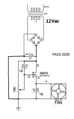
I'm in the way of building the Fan controler board, here's the schematic adapted to my configuration, I'm not sure for the 4007 diode and 100uf capa, I know the diode is meant to drop a bit of voltage and the capa to smooth it, but I wonder about the polarity.
An externally hosted image should be here but it was not working when we last tested it.
Thanks Zen Mod, I know that my lack of knowledge can seem shocking at time, I'm learning.
However, My transformer is a 2X15vac, witch is mainly meant to feed two HP protection boards, I just want to chip out the 15vac from one of the board and lower the voltage to something near the 12vdc needed by the fan before the speed controler.
BobEllis spoke about a 1N4007+100uf capa to drop the 15vdc to 9vdc. http://www.diyaudio.com/forums/pass...ld-aleph30-needs-some-help-3.html#post3786213
What I was trying to describe was a half wave rectifier. Omit the bridge, tie one side of the transformer to ground then connect the other to the diode. Add a cap and you are at roughly 0.667 x VAC. The way you had it drops 0.7 V. Nine VDC is probably enough to get your fan to start reliably. You can further slow it with the controller.
If you really want to use a bridge, 15 VAC is on the high side but the MOSFET can drop that down to something less than 12v to keep your fan quiet. You probably want a heat sink on the MOSFET.
If you really want to use a bridge, 15 VAC is on the high side but the MOSFET can drop that down to something less than 12v to keep your fan quiet. You probably want a heat sink on the MOSFET.
Last edited:
No the 100 uF goes across the cd to smooth the ripple.
And the pot also goes across the DC as in ZM sketch
And the pot also goes across the DC as in ZM sketch

An externally hosted image should be here but it was not working when we last tested it.
Do I got it right?
Like this
Arf, crossed posts 😉
But I'm glad, I got it right 😀
Thanks a lot BobEllis / Zen Mod
- Status
- Not open for further replies.
- Home
- Amplifiers
- Pass Labs
- Beginner to build an Aleph30 needs some help