R12 - yes
but value of R12 is transposing further exactly voltage resulted across R23-R26
so - do not alter their value unless you know what you're doing
tip - even if you can't grasp what's going on - just print all original Aleph schematics and study them
one of them will suit your needs , then follow it blindly
For the heatsinks, here the big babies😀
You are building a 6- device Aleph with 32V rails.
Your heatsinks are not all that big... 😱
But they will work. 🙂 🙂 🙂
one of them will suit your needs , then follow it blindly
Probably Aleph 5 or 2.
Last edited:
The sense resistor value fits into the equation, but we usually play with the smaller cheaper ones. The gain is set by the ratios of R20 to R12 and R23-26 net to R35, 37, 39 net parallel. With the sense resistors equal to half the parallel source resistors and R20= R12 we get ~50% AC gain, IIRC.
Yeah, those heat sinks are sissy sinks for the build you planned. They probably will be awful hot at 180W. Cut back to 4 pairs. Looks like store cases packaging. The 3 pair 30V rail amp needs the 5U case.
Yeah, those heat sinks are sissy sinks for the build you planned. They probably will be awful hot at 180W. Cut back to 4 pairs. Looks like store cases packaging. The 3 pair 30V rail amp needs the 5U case.
Last edited:
Maybe the pictures doesn't do those heatsinks justice, but they are 5U heatsinks (300mmx210mmx40mm) given for 0.2C°/W
I just find them huge cause I never came across heatsinks those big😛
I just find them huge cause I never came across heatsinks those big😛
4U is good up to 100W diss per side , confirmed in real life ( though , not in Bombay )
5U is for not much more ..... say 125W max
5U is for not much more ..... say 125W max
Well, I have to think of something for the cooling then..... maybe a 120mm bequiet computer fan (15db at 12V)
be quiet! Silent PSU & Cooling for your PC
Witch will be placed on the top plate of the amp in blowing mode (outside air pumped inside the chassis
with a little 30VA 2x15v (for the Speaker protections) and 1x9v (for the fan)
Transformateurs torique - Transformateur torique 30VA 2x15V + 1x09v
plus a little regulator psu to feed the fan with DC voltage
Alimentation linéaires - AMC - kit Alimentation régulée 1.5/30VDC 3A LM1085
I will make a BOM for the amp, I hope you'll be able to tell me if there's something odd with it
Save yourself a transformer and the fan controller - use the same transformer for protection circuit and fan. Set it up ct, use a bridge for +/- and a single 1n4007 followed by a small cap for the fan supply. You can make very simple fan speed control with a pot and a mosfet. You can add an extra cap across the resistor to help starting if slow speed operation becomes a problem. All fits on a small piece of perfboard. Layout not critical.
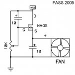
Papa posted a circuit for this many years ago, I will try to redraw it when I get home, but will try to describe it;
1N4007 and 100 uf (value not critical) cap create a ~9V supply from a 15VAC winding and ground.
10K pot connects across the 9V and ground. Can be single turn, 10 turn or 25 turn if you really like turning things.
To +9V connect the fan +
To fan - connect the drain of an n channel mosfet. General purpose anything like IRF610, IRF510, etc. (to name what's in my parts bin)
Source of mosfet to ground.
Wiper of pot to gate of mosfet.
1-10 uf from mosfet gate to V+ if needed to help startup.
The voltage at the mosfet gate controls current, which is controlled by the voltage divider created by the pot. The cap from V+ to gate creates a spike on turn on that will give the fan plenty of juice to start and then drop down to a lower running speed.
Thanks a lot BobEllis, I think I will learn a lot with this project and everybody advises 🙂 (even if some of them are still little obscure form me right now)
I'm eagerly waiting for your drawing, but I will try to understand the concept from your description.
I'm eagerly waiting for your drawing, but I will try to understand the concept from your description.
Thanks, ZM. More time this evening for 
Cowneko, all caps can be any general purpose electrolytic rated 16 V or more.
Cowneko, all caps can be any general purpose electrolytic rated 16 V or more.
Last edited:
cool, I only need to put my hand on a N mosfet (irf640 is the only one available near me) and a 1 turn 10K cermet pot (I'm a lazy one  )
)
I already got the capas and diodes
Thank you for the schematic
)I already got the capas and diodes
Thank you for the schematic
It looks like you only have one channel worth of 0R47 - 1 for each source resistor and 6 for the current sense, 12 per channel
You can't count on getting a decent match for the IRFP240 and IRF610 that need to be matched ordering the exact number. If you order a whole stick of 25 IRFP240s and state that you want all from the same lot you probably will be able to find the 4 matched triples. There are also a few sources of matched IRFP240s among our membership. Their names escape me at the moment, search other threads in the Pass forum. The IRF9610s are cheap and 20 will probably give you a couple of really good matched pairs. See the matching devices article on www.passdiy.com for how to match them.
The balance of your parts selection looks reasonable (part numbers for terminal blocks missing.) Elna Silmics might be a nice replacement for C1-3. Digikey 50V version, 604-1123-ND. at 32V rails, I'd use 50V in all places, the original BOM was based on 24V rails. Other than that, some like Dale RN60 resistors, but Papa's circuits sound nice with just about any old resistor.
Last edited:
Well, thanks a lot for your return,
Right, I forgot to add the 6 0R47 resistors for R23-R26 and R47, R48 -> corrected.
For the irfp540/irfp9610, I found a Matched set (less than 3% tolerance) on ebay (12 irfp240, 6 irf9610 and 4 ztx450 )
I added the references for the terminals on the BOM.
For C1-C3, I will have difficulty to populate silmicII capa here, the 220uf 50V are 16mm diameter but the board is designed for 12.5mm diam capas, I can maybe go to 14mm max or maybe 1 or 2 16mm plus one 12.5mm (in C1 as it seems it's the coupling capa) I'm thinking of some nichicon KZ Muse here....I'l go find something witch work here 🙂.
I'll post the new BOM as soon as I find something adequate.
Ok, I think I found good capacitors for C1-C3
Those are Nichicon FG serie (FineGold), they are 12.5mm diameter and seems to have good spec and reviews
Invalid Request
I can also bypass them with some good mkp films I have on hand (mundorf mcap, Wima, obbligato)
For the resistors I think I'll stick to vishay BC, as they are not to pricey and available (don't want to multiply the sources/shipping charges)
Attached, V2 of my BOM
Attachments
- Status
- Not open for further replies.
- Home
- Amplifiers
- Pass Labs
- Beginner to build an Aleph30 needs some help