Not daft at all.
The circuit that is the current discusion will have enough oomph to get the fan turning on power up , and then, you need only adjust to pot to make the fan silent.
Any fan makes a huge difference vs. pure convection when your sinks are on the small side.
The circuit that is the current discusion will have enough oomph to get the fan turning on power up , and then, you need only adjust to pot to make the fan silent.
Any fan makes a huge difference vs. pure convection when your sinks are on the small side.
You'd need a resistor from gate to ground to form a voltage divider. Size the resistor to make the fan just start on power up, then the NTC would increase fan speed with temperature. The catch is does the temperature coefficient lower the resistance enough to keep up with the demand?
As this is a class A amp, actively variable fan speed is moot since the heat is pretty constant. Good concept for Class AB, though. Rod Elliot has a controller on his site that uses diodes as sense elements and a comparator to drive the fan control.
As this is a class A amp, actively variable fan speed is moot since the heat is pretty constant. Good concept for Class AB, though. Rod Elliot has a controller on his site that uses diodes as sense elements and a comparator to drive the fan control.
Last edited:

As this is a class A amp, actively variable fan speed is moot since the heat is pretty constant.
And better then PP class A (as only part of the output current comes from redistributing quiescent current, at a penalty of higher distortion)
It works!!!😀
It makes for a tiny tiny little board, It works like a charm, really.
Pictures to follow
It makes for a tiny tiny little board, It works like a charm, really.
Pictures to follow
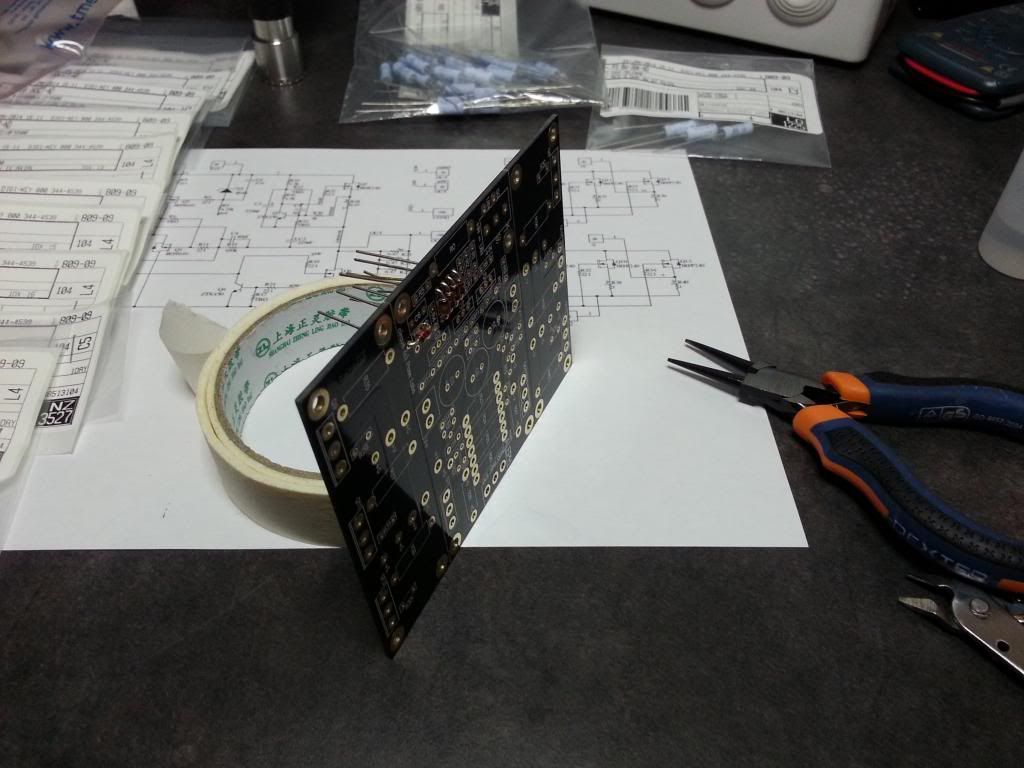
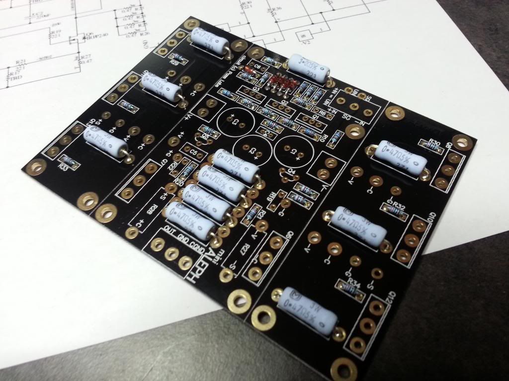
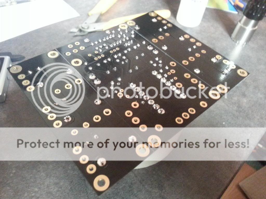
AMP board building phase
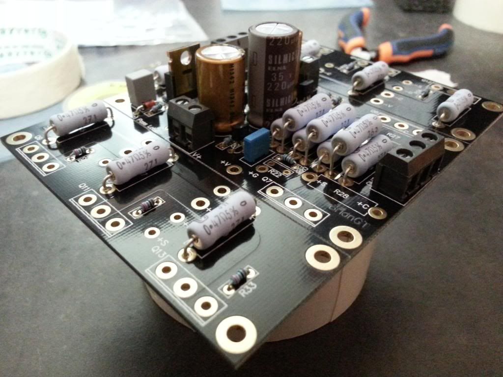
Here all the components:
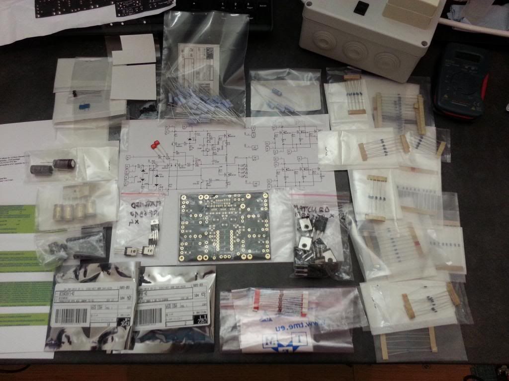
NOTE: You'll see that I already have received the fets from HK (still waiting those of h_a), and they seem at least legit to me, although, I don't know of their matching condition, this will be a good opportunity for me to learn how to match fets. For this project, I'll use the irfp240 and irf6910 from h_a.
PART LIST:(for one board)
RESISTORS
R0 RES 3 OHM 3W 5% AXIAL X1
R1.R9 RES 10K OHM 1/2W 1% AXIAL X2
R2.R15 RES 100K OHM 1/2W 1% AXIAL X2
R3.R10 RES 68.1K OHM 1/2W 1% AXIAL X2
R4.R7.R8.R11.R21.R29-R34 RES 221 OHM 1/2W 1% AXIAL X11
R5 RES 4.75K OHM 1/2W 1% AXIAL X1
R12 RES 825 OHM 1/2W 1% AXIAL X1
R13 RES 47.5K OHM 1/2W 1% AXIAL X1
R14.R16 RES 1.5K OHM 1/2W 1% AXIAL X2
R17.R18 RES 392 OHM 1/2W 1% AXIAL X2
R20 RES 1K OHM 1/2W 1% AXIAL X1
R23-R26.R35-R40. R47-R48 (R49) RES 0.47 OHM 3W 5% AXIAL (R47 and R48 are stacked between R23-R24 an R25-R26) I'll may add another one on R49 (stacked between R24-R25) X12 (or 13)
CAPACITORS
C1,C3 CAP ALUM 220UF 50V 20% RADIAL (Nichicon FG Muse) X2
C2 CAP ALUM 220UF 35V 20% RADIAL (elna silmicII) X1
C4 CAP MICA 10PF 300V 5% RADIAL X1
C5 CAP FILM 10000PF 100VDC RADIAL X1
C6 CAP FILM 0.047UF 63VDC RADIAL X1
DIODES
Z1-Z5 DIODE ZENER 9.1V 1.3W DO41 X5
TRANSISTORS
Q1 IRF9610 X1
Q2,Q3 Paired IRF9610 (from h_a on DIYAUDIO forums http://www.diyaudio.com/forums/swap...fets-your-f1-f4-f5-aleph-j-3.html#post2436167) X2
Q4,Q5 ZTX450 X2
Q8-Q13 IRFP240 sixlets (matched by h_a on DIYAUDIO forums http://www.diyaudio.com/forums/swap...fets-your-f1-f4-f5-aleph-j-3.html#post2436167) X6
OTHERS
Terminal post V-/V+ 2ways 5mm screw type X2
Terminal post IN / OUT 3ways 5mm screw type X2
Some wires to connect the fets board to the amp board (OFC)
BUILDING:
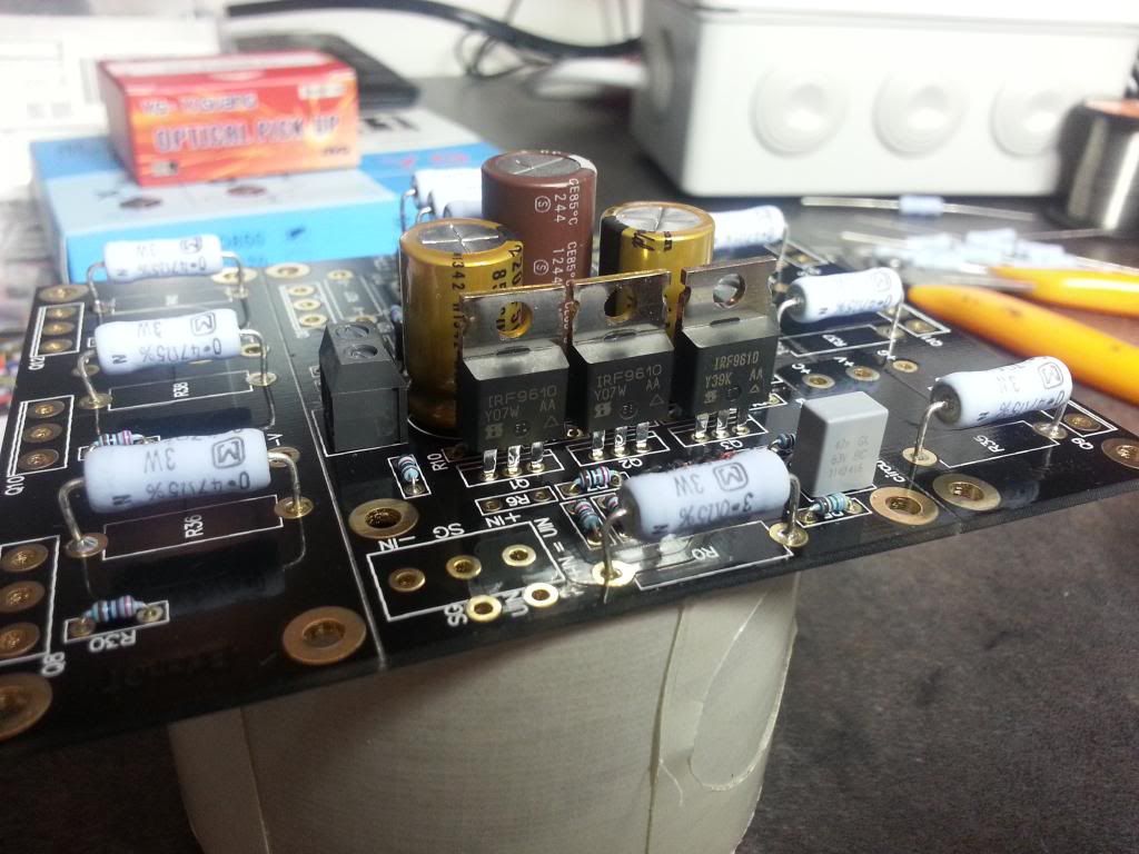
As for the PSU, I took the time to clean the contacts with isopropanol, I've cleaned the component legs too.
As usual, start with small components then go bigger.
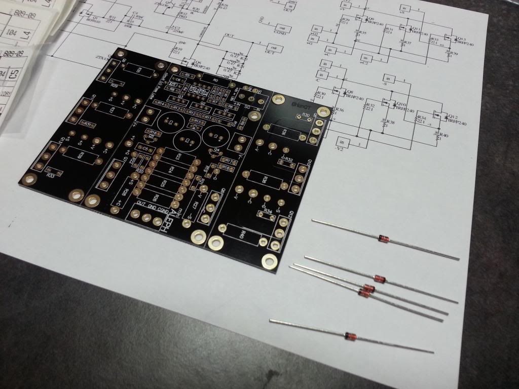
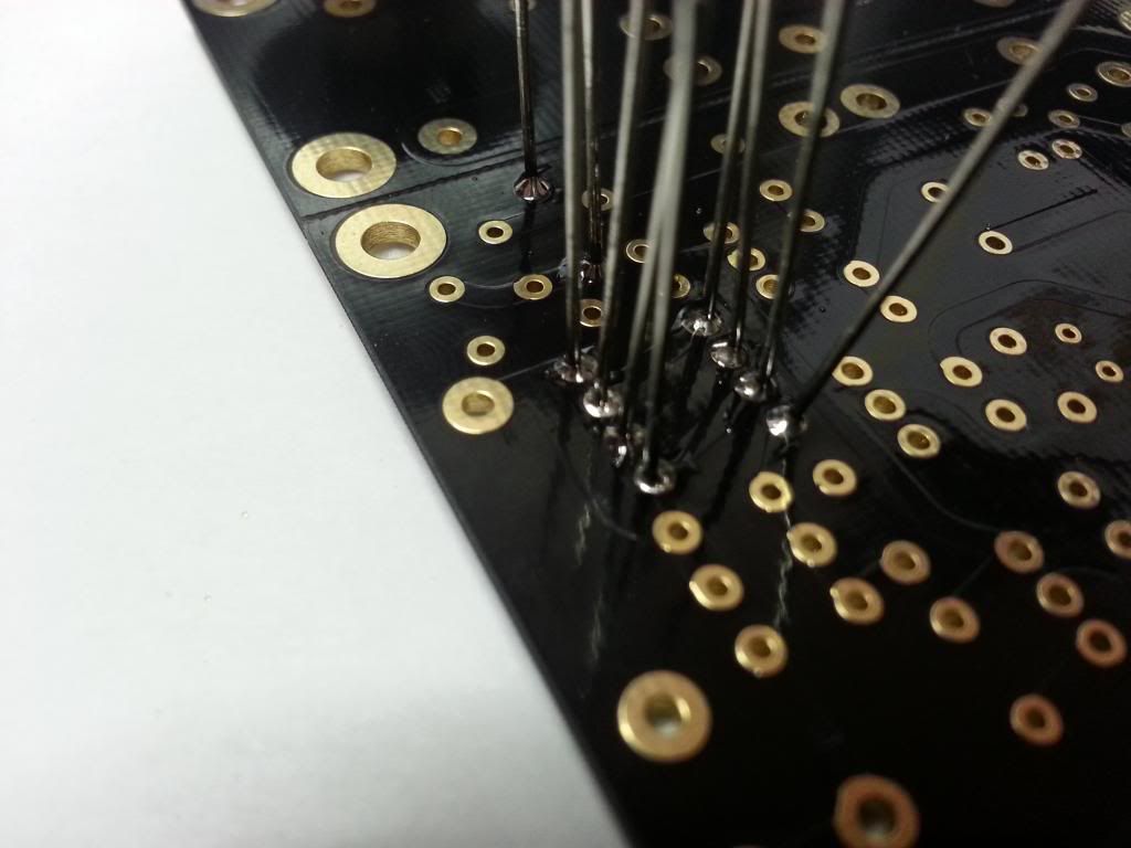

This is my procedure for soldering (Z1-Z5 diodes) pay attention to the polarity.
Soldering the 1/2W resistors
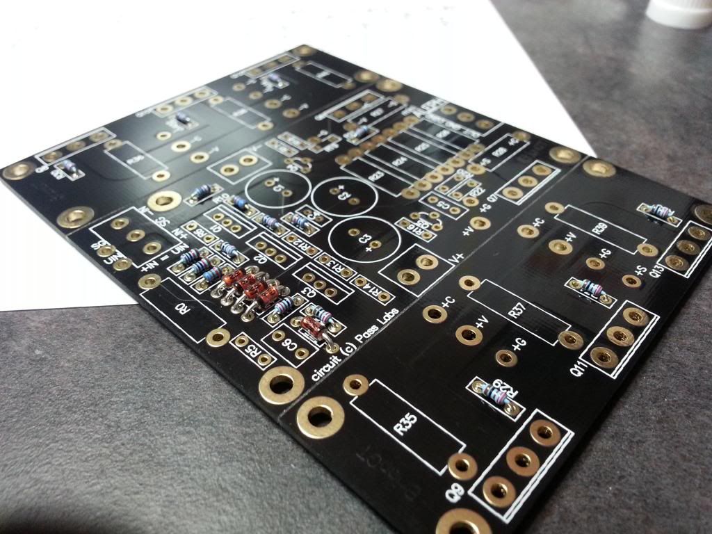
Soldering the 3W 0R47 resistors, I try as much as possible to solder the components with value upward, witch will facilitate troubleshooting
Soldering the film caps and non matched transistors (pay attention to the polarity of the transistor, Emitter, Base, Collector)
Soldering the Elco capacitors (watch for their polarity) and the V-/V+ terminal posts.
that's it for now 😀

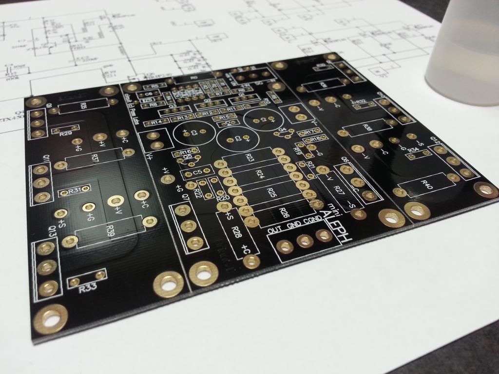
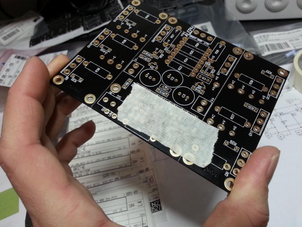
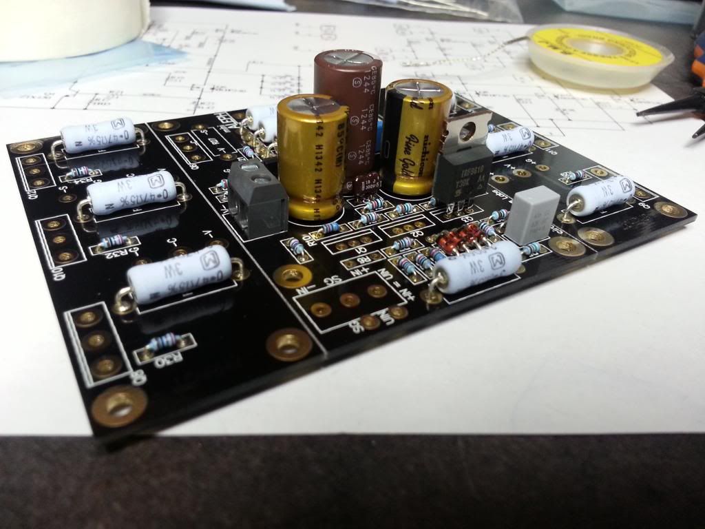
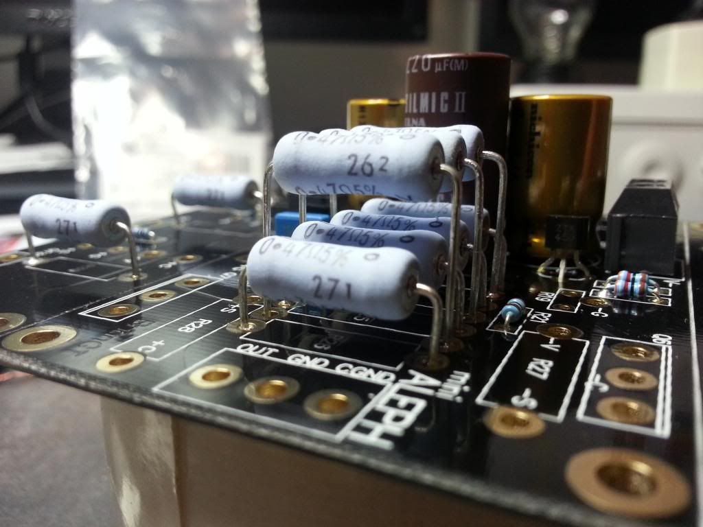
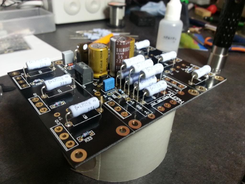
Here, a test fit for R47-R49, I think I must install R47 and R48, but shall I install R49?
I put the signal terminal posts without soldering them, I don't know yet if I will use them or not.
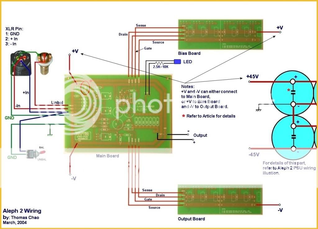
Speaking of Inputs, I want to use balanced XLR inputs as well as unbalanced RCAs, how can I manage those two different inputs at the same time (RCA to UIN and SG, XLR to -IN, +IN and SG), shall I use a switch to swap from RCA and XLR, by linking it to +IN and SG (knowing I'll never use the two at the same time)?
Like this
Here all the components:

NOTE: You'll see that I already have received the fets from HK (still waiting those of h_a), and they seem at least legit to me, although, I don't know of their matching condition, this will be a good opportunity for me to learn how to match fets. For this project, I'll use the irfp240 and irf6910 from h_a.

PART LIST:(for one board)
RESISTORS
R0 RES 3 OHM 3W 5% AXIAL X1
R1.R9 RES 10K OHM 1/2W 1% AXIAL X2
R2.R15 RES 100K OHM 1/2W 1% AXIAL X2
R3.R10 RES 68.1K OHM 1/2W 1% AXIAL X2
R4.R7.R8.R11.R21.R29-R34 RES 221 OHM 1/2W 1% AXIAL X11
R5 RES 4.75K OHM 1/2W 1% AXIAL X1
R12 RES 825 OHM 1/2W 1% AXIAL X1
R13 RES 47.5K OHM 1/2W 1% AXIAL X1
R14.R16 RES 1.5K OHM 1/2W 1% AXIAL X2
R17.R18 RES 392 OHM 1/2W 1% AXIAL X2
R20 RES 1K OHM 1/2W 1% AXIAL X1
R23-R26.R35-R40. R47-R48 (R49) RES 0.47 OHM 3W 5% AXIAL (R47 and R48 are stacked between R23-R24 an R25-R26) I'll may add another one on R49 (stacked between R24-R25) X12 (or 13)
CAPACITORS
C1,C3 CAP ALUM 220UF 50V 20% RADIAL (Nichicon FG Muse) X2
C2 CAP ALUM 220UF 35V 20% RADIAL (elna silmicII) X1
C4 CAP MICA 10PF 300V 5% RADIAL X1
C5 CAP FILM 10000PF 100VDC RADIAL X1
C6 CAP FILM 0.047UF 63VDC RADIAL X1
DIODES
Z1-Z5 DIODE ZENER 9.1V 1.3W DO41 X5
TRANSISTORS
Q1 IRF9610 X1
Q2,Q3 Paired IRF9610 (from h_a on DIYAUDIO forums http://www.diyaudio.com/forums/swap...fets-your-f1-f4-f5-aleph-j-3.html#post2436167) X2
Q4,Q5 ZTX450 X2
Q8-Q13 IRFP240 sixlets (matched by h_a on DIYAUDIO forums http://www.diyaudio.com/forums/swap...fets-your-f1-f4-f5-aleph-j-3.html#post2436167) X6
OTHERS
Terminal post V-/V+ 2ways 5mm screw type X2
Terminal post IN / OUT 3ways 5mm screw type X2
Some wires to connect the fets board to the amp board (OFC)
BUILDING:
As for the PSU, I took the time to clean the contacts with isopropanol, I've cleaned the component legs too.
As usual, start with small components then go bigger.


This is my procedure for soldering (Z1-Z5 diodes) pay attention to the polarity.

Soldering the 1/2W resistors

Soldering the 3W 0R47 resistors, I try as much as possible to solder the components with value upward, witch will facilitate troubleshooting

Soldering the film caps and non matched transistors (pay attention to the polarity of the transistor, Emitter, Base, Collector)

Soldering the Elco capacitors (watch for their polarity) and the V-/V+ terminal posts.

that's it for now 😀


Here, a test fit for R47-R49, I think I must install R47 and R48, but shall I install R49?
I put the signal terminal posts without soldering them, I don't know yet if I will use them or not.
Speaking of Inputs, I want to use balanced XLR inputs as well as unbalanced RCAs, how can I manage those two different inputs at the same time (RCA to UIN and SG, XLR to -IN, +IN and SG), shall I use a switch to swap from RCA and XLR, by linking it to +IN and SG (knowing I'll never use the two at the same time)?
Like this

Completely awesome so far! The photos are wonderful!
I'm looking forward to each step you make - it's great to watch.
🙂 🙂 🙂
I'm looking forward to each step you make - it's great to watch.
🙂 🙂 🙂
Completely awesome so far! The photos are wonderful!
I'm looking forward to each step you make - it's great to watch.
🙂 🙂 🙂
Thanks a lot 6L6, your comments pushes me forward

nice
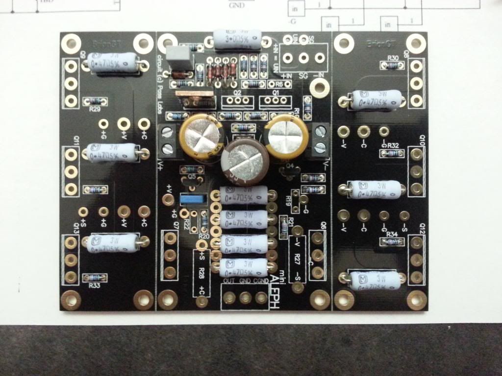
next time rise those 3W Pana at least 3mm from pcb
Thanks a lot for this advice, I have lots of 0R47 res at hand, I will change them (with the 3mm gap) and use the old ones on upcoming project 😉
I put them flush on the PSU too, is it really a big problem here too? Must I change them? (Just note, that the big fan will blow right at the psu)
Last edited:
you don't need to change them - even Pa is putting them ditto on pcb in FW and PL products
that's I'm just splitting da hair

that's I'm just splitting da hair
Zen Mod, as a teacher myself (in CGI, not electronic, everybody would have noticed 😛) I can't demand my students to be "good" students if I won't behave like one myself.
So, here we go!

Just a little piece of card board for separating the res from the pcb😉
Un-soldering job was quite easy, thanks to the incredible quality of Brian's boards.

This one's a bit blurry
So, here we go!

Just a little piece of card board for separating the res from the pcb😉
Un-soldering job was quite easy, thanks to the incredible quality of Brian's boards.


This one's a bit blurry

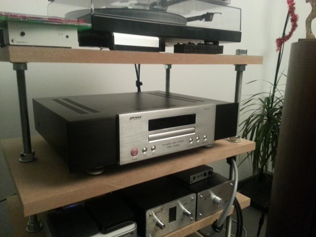
My last acquisition, an Advance Acoustic CDM203II cd player.......arghhhh what a sound!! even with the chinese tubes.
I'm waiting for matched Sovtek 12AX7LPS to make that player even better
I really made a bargain on this, only 90€ in perfect state (as mint), I really think the Easy cash where I find this jewel does not have any clue of what they were selling.....good for me.
PS: I also ordered some spare optical pickup units (15$ each) as I know that the drive is, well capricious to be polite.

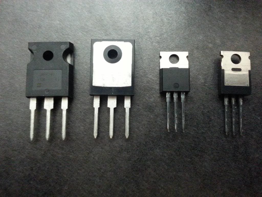
Yeah, h_a Fets finally arrived this morning 😀
Thanks a lot Hannes!! The packaging is incredible (as opposed to HK fets witch where packaged in a simple zip bag)
Here the bad boyz

Then........
Thanks a lot Hannes!! The packaging is incredible (as opposed to HK fets witch where packaged in a simple zip bag)
Here the bad boyz

Then........

- Status
- Not open for further replies.
- Home
- Amplifiers
- Pass Labs
- Beginner to build an Aleph30 needs some help