I have been experimenting with the J113. 47 ohm resistors gives about 40% reduction in idle current. 68 ohms give almost exactly 50% reduction in idle current.
The actual current will depend on the JFETs in your hand. You have to measure Idss of some of them and then try out some degen resistors to see what happens. Then make a decision.
With this layout, you can adjust every cell for 10mA. You just need a wide selection of resistors between 30 ohms and 100 ohms, give or take.
If I were you I would first set some performance targets.
For example, what bias for a power follower, and what Zout to accept.
Then see how realistic they are with a certain device.
Assuming you use 1000 J113s per channel, so 500x in parallel.
And let's say you accept a bias of 2A.
Then each FET should not be running at 4mA.
You might find that you need a bigger source resistor than 100R.
Then your transconductance per J113 is ~6mS, or equivalent to 160R.
Add (the not quite sufficient) 100R on top, you get 260R per FET.
Divide that by 500, your Zout is ~0.5R.
Would those numbers be acceptable to you (or others) ?
Cheers,
Patrick
If I were you I would first set some performance targets.
For example, what bias for a power follower, and what Zout to accept.
Then see how realistic they are with a certain device.
Assuming you use 1000 J113s per channel, so 500x in parallel.
And let's say you accept a bias of 2A.
Then each FET should not be running at 4mA.
You might find that you need a bigger source resistor than 100R.
Then your transconductance per J113 is ~6mS, or equivalent to 160R.
Add (the not quite sufficient) 100R on top, you get 260R per FET.
Divide that by 500, your Zout is ~0.5R.
Would those numbers be acceptable to you (or others) ?
Cheers,
Patrick
Hi Patrick. Thank you for your experienced advice. I have been thinking along those lines.
My first goal is to make some 80-cell versions and test them for all of the parameters that you mentioned above.
I think that the 80-cell through-hole layout will work for any headphone and some flea-power speaker applications.
Running at 10mA is not a requirement. Nelson's J113 48-cell version is using 47 ohm resistors. I think that brings the idle current at or above 12mA for each JFET on average.
After the 80-cell board is characterized, I will consider the next step.
Rail to rail SE buffer
I am thinking about a rail-to-rail single ended JFET buffer. I stumbled upon a nice JFET for Q2 and Q3 but the max voltage is 1/2 of the J113. I would like to achieve near rail-to-rail swing.
Will something like this work?
I assume a capacitor belongs across R2 or R3.
I am thinking about a rail-to-rail single ended JFET buffer. I stumbled upon a nice JFET for Q2 and Q3 but the max voltage is 1/2 of the J113. I would like to achieve near rail-to-rail swing.
Will something like this work?
I assume a capacitor belongs across R2 or R3.
Attachments
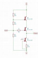
R2 and R3 ref. to output, R4 not needed, cap across R3
don't fret, I had posted much greater stupidities, over the years 🙂
don't fret, I had posted much greater stupidities, over the years 🙂
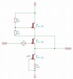
Use depletion Mosfet for Q3, connect gate through a 220R to source of Q2. There is a TO92, TO220 and TO243AA(SOT89) version of DN2540 family; and BSP129, BSP135, BSP149 and BSP179 in SOT223. A few from Ixys like IXTP08N50D2 in TO220.
R2 and R3 ref. to output, R4 not needed, cap across R3
don't fret, I had posted much greater stupidities, over the years 🙂
Like this? Yes I see your point.
Very nice of you. Thanks.
Q2 can be a garden variety BJT I suppose.
Attachments

The cap is IMHO a bad idea.
I suggest you take a close look at Calvin's hybrid-compound-super-buffer.
hybrid-buffer - calvins-audio-pages
Patrick
I suggest you take a close look at Calvin's hybrid-compound-super-buffer.
hybrid-buffer - calvins-audio-pages
Patrick
cap was good for Allen Wright in his SLCF, practically taken from Tec scopes of tube era
not saying that there are no better ways
not saying that there are no better ways
I can breadboard with and without cap. Thanks for the suggestions.The cap is IMHO a bad idea.
I suggest you take a close look at Calvin's hybrid-compound-super-buffer.
hybrid-buffer - calvins-audio-pages
Patrick
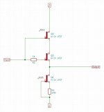
If you pick a Q2 with high Idss and high Vp you can use it as a cascode without
the caps and resistors, just attach its gate to input through a gate stopper resistor.
J11 is a candidate, maybe J112

the caps and resistors, just attach its gate to input through a gate stopper resistor.
J11 is a candidate, maybe J112

If you pick a Q2 with high Idss and high Vp you can use it as a cascode without
the caps and resistors, just attach its gate to input through a gate stopper resistor.
J11 is a candidate, maybe J112
Thank you. Like this?
Attachments
did you read papers from Borbely site, I posted link to?
Yes. I downloaded and read through them. It will take some time to all sink in.
I have all the parts for the latest suggestion from Mr. Pass. I will breadboard it and post a scope shot of max p-p output.
Borbely's fave way of cascoding was exactly what Pa wrote in #213
and it's well explained in his "JFet frontiers....." articles
and it's well explained in his "JFet frontiers....." articles
Borbely's fave way of cascoding was exactly what Pa wrote in #213
and it's well explained in his "JFet frontiers....." articles
I will go back over it and read it again. Thanks.
Breadboarding anything people throw at you is not going to get you very far, if you do not spend them to understand them first.
The understanding you have to do yourself. People can't help you.
This would be my last bit of advice.
Success,
Patrick
The understanding you have to do yourself. People can't help you.
This would be my last bit of advice.
Success,
Patrick
Breadboarding anything people throw at you is not going to get you very far, if you do not spend them to understand them first.
The understanding you have to do yourself. People can't help you.
This would be my last bit of advice.
Success,
Patrick
Trying to learn some circuit designing, some PCB layout and sharing the journey. Trying to add to the skill stack.
There appears to be enough community interest to take some of these ideas to a finished project. Working through a few different variations with some different devices.
Three variations seem to be taking form
1. Original NP complementary Beast.
2. Single-ended B1
3. Cascode single-ended B1
1. and 2. are being fabbed. 3. is just an idea. Mr. Pass's latest suggestion helps move 3. along.
Thanks for your advice.
- Home
- Amplifiers
- Pass Labs
- Beast with 1000 JFETs redux?