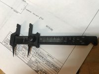
Resistor Lead Bending Tool | Production Devices
Can be interesting tools 3 pcs. 800K kit 🙂 ..Or find some similar model(s) Best regards
That is cool. Thanks
For the price, they are a good buy and makes the board look more professional with each resistor, diode etc bent exactly the same at a nice right angle.
Resistor Lead Bending Tool | Production Devices
Can be interesting tools 3 pcs. 800K kit 🙂 ..Or find some similar model(s) Best regards
Great tip. This cheap tool lasts forever and saves a lot of time. I love mine

With a 220k resistor from input to ground, the output offset is either large negative or large positive and not the same every time the PCB is turned on.
The offset problem turned out to be a input resistor problem. With a 1k input resistor, no more wandering output offset
35 complete cells populated. 2 cells 1/2 populated. 560 mA idle current. output offset 13mV.
Progress is happening.
The offset problem turned out to be a input resistor problem. With a 1k input resistor, no more wandering output offset
35 complete cells populated. 2 cells 1/2 populated. 560 mA idle current. output offset 13mV.
Progress is happening.
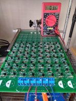
48 cells populated. Idle current 730 ma. Output offset voltage single digit millivolts.
Building one cell at a time is instructive. I check output offset and choose the next pair to move the offset closer to zero volts.
If I fully populate this PCB, it should end up around 1.2A. I plan to stop as close to 1A as possible.
Building one cell at a time is instructive. I check output offset and choose the next pair to move the offset closer to zero volts.
If I fully populate this PCB, it should end up around 1.2A. I plan to stop as close to 1A as possible.
Attachments
What are your thoughts on going single ended? N-JFETs here are half the price of P-ones. If going with 100 fets, could one compensate differences in individual fets with source resistor of certain value, if very close matching is not desired?
What are you using to hold the PCB? Looks pretty handy.48 cells populated. Idle current 730 ma. Output offset voltage single digit millivolts.
What are your thoughts on going single ended? N-JFETs here are half the price of P-ones. If going with 100 fets, could one compensate differences in individual fets with source resistor of certain value, if very close matching is not desired?
I have a single ended version PCB in-hand. Look back in the thread for the single ended version.
You can use all N JFETs or all P JFETs. I will not be building it until I have the complementary version complete.
Yes you can change the source resistors to make every JFET Idss exactly some value. ...or... you can treat them as a group and match the group.
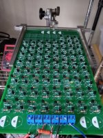
What are you using to hold the PCB? Looks pretty handy.
I bought it at a flea market decades ago. It was used by a pinball repairman. It is a Technical Devices PCB Holder. It is cantilevered with 4 detentes. It is easy to flip over and remains horizontal in either position. It has a quick release mechanism.
I have a single ended version PCB in-hand. Look back in the thread for the single ended version.
You can use all N JFETs or all P JFETs. I will not be building it until I have the complementary version complete.
Yes you can change the source resistors to make every JFET Idss exactly some value. ...or... you can treat them as a group and match the group.
Ok, thanks. Thing that appeals me in this project is actually cost - I find heatsinks the least available part, this looks like a great alternative to try out.
Ok, thanks. Thing that appeals me in this project is actually cost - I find heatsinks the least available part, this looks like a great alternative to try out.
Yes agreed. In addition, this project creates a pair of complementary power JFET amplifier. You cannot buy complementary power JFETs. JFETs are more linear than MOSFETs.
Weight and cost are also advantages compared to a class A DIY MOSFET amp.
66 1/2 cell populated. 1A idle current. Less than 10mV output offset.
Connected signal generator and oscilloscope. My sig gen cannot drive this beast. The sig gen runs out of current on the negative going 1/2 of the sine wave at maximum voltage of the sig gen.
This beast will require a low impedance buffer if your preamp does not have a low output impedance.
Connected signal generator and oscilloscope. My sig gen cannot drive this beast. The sig gen runs out of current on the negative going 1/2 of the sine wave at maximum voltage of the sig gen.
This beast will require a low impedance buffer if your preamp does not have a low output impedance.
Attachments
told ya that you need local governor
If I choose a governor, will I have to buy him/her a mansion?

- Home
- Amplifiers
- Pass Labs
- Beast with 1000 JFETs redux?