ostripper said:
Thank you for comment but with knowledge comes headaches🙁
As far as this topology, Dr. bora is right about simulators,
they are only an "approximator". Lucky for me , I have
2 "real' working amps with this topology and can
see behaviors of different device choices. Some devices,
such as the new fairchild ksa1381, saturate very easily at
clipping giving a very harsh result (but no)with
plenty of H5/7/9+etc.
I've tried the new ksa350/40's both in virtual and real world.
they saturate much less but you end up with a"slower" amp.
I'd like to try dr. bora's 2sc2240 but they are hard to find.
(except SMD , which I might go to next..more choices 🙂)
The models are getting better, I can see a notable difference
between the "old" 340/350 model and the KSA clones as
the new model has saturation characteristics included.
BTW - I'm "stealing" bits and pieces of the design and the
improvements are impressive.
OS
Done a little work on his amp after wiping the slep from my eyes. There are some real odd things in the Sim that has to be confirmed, T^he front end is not working quite to my satisfaction.
I am a great supporter of professional sim packages like MicroCAP, but at $ 5K it is not in reach of every DIYselfer.
We have several packages and I must admit, feeding it with the correct data, spread and tolerances of components and performing monte carlo brings you so close to the real thing that only the 4th decimal place starts to creep. You will ten to one find that the problem is with the measurement instrument.
Harmonics tally with the HP spectrum analiser and if you get a wrong reading, check the connecting cables for the fault or your measurement technique is incorrect or you have calculated something badly.
I grew up with MicroCAP since 1980 and our companies design department relies very much on it to turn out a product quickly and correctly. Our motto is right first time and I must vouch that after simulation I lay a PCB populate it and turn it on and it works as specified first time.
If MicroCAP tells me the harmonic lie at 140 dB down, I know that I will have to take every precaution calibrating the spectrum analyzer to be able to detect these signals at the noise floor.
Measuring down to theoretical limits is very difficult. One often have to add 20 dB linear amplifiers and then calibrate their effect out of the measurement.
This is simply not the case. I already pointed out that I tried the MJE340/350 in place of the 2SA1381/3503 in your amp and experienced worse clipping behaviour.
Exactly, I do not trust the sims entirely, now that I have
the next "Multisim" NI circuit design pro 10. IT does not exhibit
this behavior with the 1381's as LT4 does.. So for
this type of thing I guess the real thing driven
to clipping and the CRO is the only way to confirm this.
OS
BTW, thank you dr. bora, penn. usa/UPS no minimum order..
lots of original japanese transistors..
ostripper said:Exactly, I do not trust the sims entirely, now that I have
the next "Multisim" NI circuit design pro 10. IT does not exhibit
this behavior with the 1381's as LT4 does.. So for
this type of thing I guess the real thing driven
to clipping and the CRO is the only way to confirm this.
Checking the Multisim Component Reference Guide shows that it does not recognize the quasi-saturation parameters of the KSA1381/KSC3503 models from Fairchild. So it's probably just ignoring those particular parameters and giving optimistic results. These are PSPICE extensions supported by LT (and MicroCap and others) but not NI.
You need to implement a clamping circuit to fix the clipping behavior of FA. In Bob Cordell's amp article, this is Figure 8, and the relevant components are Q18, Q19, D5, D6 and others. But that's a subject for the FA thread.
Of course, when I said I swapped MJE's for the 2SA/C's I meant in the actual amp, not the sim. Driving it to clipping (at +/-72VDC rails) had the MJE's behaving much worse, sticking harder top and bottom.
By MJL - Of course, when I said I swapped MJE's for the 2SA/C's I meant in the actual amp, not the sim. Driving it to clipping (at +/-72VDC rails) had the MJE's behaving much worse, sticking harder top and bottom.
You can't just "swap' 1381's with MJE's, the circuit needs to
be rebalanced.. (loop gain Re's in both input stage and VAS)
By andy C. -Checking the Multisim Component Reference Guide shows that it does not recognize the quasi-saturation parameters of the KSA1381/KSC3503 models from Fairchild. So it's probably just ignoring those particular parameters and giving optimistic results. These are PSPICE extensions supported by LT (and MicroCap and others) but not NI.
I realized that by editing the 1381 models ..no change in
results , like ,as you say MS10 ignores these parameters.
Stlll , I like the real time interaction and PCB functionality
of MS10.. I'll have to get MCap next (ahem)..try that..😀
OS
ostripper said:
You can't just "swap' 1381's with MJE's, the circuit needs to
be rebalanced.. (loop gain Re's in both input stage and VAS)
Really? This is the VAS we are talking about here, right? Tell me, what would you change to accommodate the swap?
To go from 1381 to mje350
lower the Re's for the differential to 47 instead of 100r(increase loop gain for lower beta 350's ) reduce main Re for VAS itself
by 33% (100R to 68R) mje's have less current gain.
AS you may have already reduced current in vas of fa2 i'm
just giving you a "feel" for their differences to get basically
the same electrical (current) and performance (loop gain,
unity gain point) for both variants. Sim it..and see..
😀 OS
ostripper said:
Sim it..and see..
Oh, I have. Surprise, I found not much difference in the loop gain plots.

Not enough to warrant changing resistance values to check clipping performance.
Remember, it's not overall amp performance that I'm talking about here, just the clipping behaviour.
By MJL - Oh, I have. Surprise, I found not much difference in the loop gain plots.
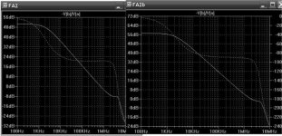
And here we go back to Andy's statement that MS9/10
"ignores" certain data from the 1381 model.. I also tried
most of fairchilds KSA- XX (high voltage amp trannies)
with the same results.. I am downloading microcap 9 pro
now and will confirm this .
I see an 6 DB gain difference on LT4 ,but on yours (ms)
not much change .. so you tell me ..
OS
Attachments
ostripper said:
.. so you tell me ..
OS
It's still simulation as opposed to real life, OS. The clipping performance was worse on my version of your amp running the MJE's. Mine is running a lower VAS current and has the Zetex diff pair plus a few other differences.
Like I said before, sticking during clipping is hard to avoid. It was a problem on my Patchwork and I added clamps to control it. It is not a problem on my Abomination amp for some reason. There is some sticking, but I'm WAY over voltage for it to show.
By dr. nico - I am a great supporter of professional sim packages like MicroCAP, but at $ 5K it is not in reach of every DIYselfer.
Got it.. will see why it is 5k$$😀 😀
OS

boraomega said:I'll probably try this in the near future. 😎
Dr.Bora, just a couple of questions on your suggested schematic:- What available transistors could be substituted for the 2SB/2SD devices, which are now almost fake everywhere?
Is R30 or R31 the variable resistor for setting Iq?
Can C1 be decreased and R26 increased to enable a better quality cap being used? I guess C5 may have to be dimensioned accordingly. Thanks.
Hi Samuel,
*There are a waste number of appropriate transistors to replace 2SB/2SD oldies. I personally like and mostly use 2SC3423/2SA1360 but any of following pairs should do the job:
2SC4793/2SA1837
2SC3601/2SA1407
2SC3955/2SA1540
2SC5171/2SA1930
Etc… etc… etc…
Through time, I used most of them and they are all good, but they are not always available to me.
*R31 is setting BIAS and should be replaced with 1k multiturn trim pot in practical circuit.
*Replace C1=10uF with 2,2uF, R26 use 470 ohms and C5 use 150pF
After sleepless night, I am still trying to decipher “bxcvb”… 
KGB and CIA experts gave up around 4AM this morning, but I am a stubborn one…
Lazy cat, what to hell is this supposes to mean? 😕 😀
KGB and CIA experts gave up around 4AM this morning, but I am a stubborn one…
Lazy cat, what to hell is this supposes to mean? 😕 😀
 Happy New year to all of you guys.
First of all I have to appologize for not responding so long; I have moved to new location and had very busy time around hollidays.
boraomega:
After sleepless night, I am still trying to decipher “bxcvb”…
KGB and CIA experts gave up around 4AM this morning, but I am a stubborn one…
Lazy cat, what to hell is this supposes to mean?
 Sorry. My first attempt to post a reply and pressed submit instead preview button, too tired I suppose ... 😴
 I'm impressed of development of this thread. Congratulations to all of you and I hope some new amp will be result at the end.
And now something completely different to little tickle your grey cells 
Specifications:
- balanced input
- galvanic insulation from preamp
- simple passive VAS
- no global feedback
- offset and bias calibration
- no output relay
- mute (Zout=high) / play (Zout=low) switch
- no power-on pop-ups
- BIGBT output stage
- +20dB voltage gain
An externally hosted image should be here but it was not working when we last tested it.
Specifications:
- balanced input
- galvanic insulation from preamp
- simple passive VAS
- no global feedback
- offset and bias calibration
- no output relay
- mute (Zout=high) / play (Zout=low) switch
- no power-on pop-ups
- BIGBT output stage
- +20dB voltage gain
- Status
- Not open for further replies.
- Home
- Amplifiers
- Solid State
- Balanced IGBT for amplifier output