Does it make any sense to build a an inductor loadad SIT follower? Just like a Mofo? Or, does the high price of the SiT device not justify the gain? (I assume that with no voltage gain, the improvement in SQ is not worth the pain)
On the other hand, perhaps it is worth trying to use an inductor in a common Source configuration, though I think that in this case a cheap smps 19v power supply may inject too much noise on the input...
On the other hand, perhaps it is worth trying to use an inductor in a common Source configuration, though I think that in this case a cheap smps 19v power supply may inject too much noise on the input...

The SIT-NFET muff shown in last schematic of "Burning Amp 2022 – Simple DIY SIT Power Amplifiers" has a potential hazard. If the negative output is accidentally shorted to ground, the current through the FETs will become very high, probably destroying the NFET, since the Tokin is more robust. An XA25 style protection circuit could prevent this hazard.
Attachments
The SIT-NFET muff shown in last schematic of "Burning Amp 2022 – Simple DIY SIT Power Amplifiers" has a potential hazard. If the negative output is accidentally shorted to ground, the current through the FETs will become very high, probably destroying the NFET, since the Tokin is more robust. An XA25 style protection circuit could prevent this hazard.
drek is going to hit a fan with any bridged amp, if you do the same
and people are making them all the time
heh, even Anvil isn't idiot-proof

I am exploring some variations on the SIT-NFET muff topology.
- Use a current bias servo that functions with small values for the voltage across R1 and R2. This seems to preclude the use of an optocoupler circuit.
- Allow R1 to be smaller or even eliminate it. This makes the accidental Out- to ground short more dangerous.
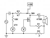
From "Burning Amp 2022 – Simple DIY SIT Power Amplifiers":
Since R1 degenerates the NFET or PFET, it is easy to use N x FETs in parallel with R1*N for the source resistors and not have a current hogging problem. This allows the use of N x cheap PFETs with the SIT-PFET muff topology.
Lastly, here is an alternate to the last schematic which gives about the same
performance, a variation of the MUFF which uses an N channel Mosfet.
This is attractive because it is easier/cheaper to buy good high power N channel
Mosfets than P channels.
Since R1 degenerates the NFET or PFET, it is easy to use N x FETs in parallel with R1*N for the source resistors and not have a current hogging problem. This allows the use of N x cheap PFETs with the SIT-PFET muff topology.

so if we still use the N channel mosfet, should like this?(Snicker) He said SIT-PFET MUFF....
😛
Attachments
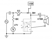
By taping the output from between the .2ohm resistors are
we able to get an output curent larger than the bias curent ?
we able to get an output curent larger than the bias curent ?
This MUFF was perfect on my SIT:Snicker) He said SIT-PFET MUFF....
😛
Considering the attached circuit at 3A and 60V the power will be 180W. With one .21 C/W heat sink per channel the temperature rise above ambient will be close to 40 degrees Centigrade (easily ~60). Maybe the SIT should go on one such heat sink and the MOSFET on another, ending up with mono blocks. What are the boyz’ experience here?
Attachments

If you want the fan speed to be continuously variable, so that it runs slowly (or not at all) when the room is cool, and only as fast as necessary when the room is warm,
AND if you also want to avoid high frequency digital signals (pulse width modulation) near your gear, then perhaps this may be worth considering
LINK: Fan inside audio chassis: variable speed, temperature controlled, analog. No PWM
AND if you also want to avoid high frequency digital signals (pulse width modulation) near your gear, then perhaps this may be worth considering
LINK: Fan inside audio chassis: variable speed, temperature controlled, analog. No PWM
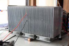
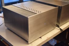
I built my BAF 2015 style THF-51S amps with fan cooling and they are barely warm to touch when running. I spent many hours, days, researching how to get rid of the heat passively, but finally had to admit that the best way was forced air cooling. I found some used heatsinks which were built for this and used DC computer fans running at low voltage, so they are very quiet. I also shrouded the heatsinks to direct the air flow through the heatsinks for better cooling efficiency.
Attachments
- Home
- Amplifiers
- Pass Labs
- BAF 2022 SIT AMPS