I refer you all to this thread: https://www.diyaudio.com/community/threads/forced-cooling-a-class-a-amp.385221/post-6996359


Uh Oh. I wonder if we crashed the Nelson interview. Everything else plays but halfway through his discussion of FR drivers I got the spinning wheel of death!
That's a good copy Paul.😉 I have 4 matched thf 51s, too. BUT It has to be a finished product preferrably in brain-dead kit form for me to consider. It seems my days have become 4 hrs long, I don't know where the time goes.I bought 4 of the THF-51S parts when the whole "While They Last" thread was first started. Since my DIY skills more or less boil down to being able to solder and follow instructions, I don't really understand the circuits Nelson shared in the PDF. Specifically, can somebody tell me what the things I've noted in these JPEGs taken from the presentation mean? And I for one would be REALLY appreciative if one of the more accomplished members of the forum would actually share a complete circuit, with part specifications, that would make use of the THF-51S parts.
Has there been anything posted about the new differential input front ends for the common drain SIT Amps? In the video at about the 39min, 45sec point, Nelson showed a piece of paper containing a schematic and a PCB.
Last edited:
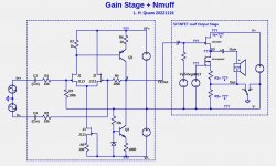
I did a screen grab of the schematic from the video and generated an LTSpice simulation.
It looks very good. I loaded the output with an 13nF capacitor which is about right for the gate of the common drain 2SK18ES.
It looks very good. I loaded the output with an 13nF capacitor which is about right for the gate of the common drain 2SK18ES.
Attachments

I'll bet you twenty dollars that Nelson's version does NOT include any PNP transistors in the TO-126 / TO-225 package. No KSA1381s, no BD140s, no 2SB882s, no KSA1220As.
You might be right, but with the higher rail voltages, the power dissipation of the BJT will be more the 200mW which is more than I like with TO-18 parts. The KSA is a $0.56 part. The KSA also has excellent gain and bandwidth.I'll bet you twenty dollars that Nelson's version does NOT include any PNP transistors in the TO-126 / TO-225 package. No KSA1381s, no BD140s, no 2SB882s, no KSA1220As.
In the schematic of post #108, don't Q2 and J4 dissipate the same amount of power? If a TO-92 is okay for J4, isn't a TO-92 also okay for Q2?
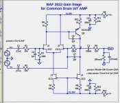
I have solved the issue with the NFET muff Out- being "hot". You can float the power supply negative side V- and ground Out-. With a minor modification to the BAF 2022 SIT AMP gain stage the circuit behaves the same either with V- at ground or Out- at ground.
Below is the schematic, with the idealized Nmuff output stage.
Below is the schematic, with the idealized Nmuff output stage.
Attachments
Stasis FE deleting Vbe thingie and few resistors at end......... same Kitchen table
https://www.diyaudio.com/community/threads/new-stasis-front-end.363701/
https://www.diyaudio.com/community/threads/new-stasis-front-end.363701/
Thanks ZM. I had not looked closely at that thread. Interesting that I chose the same 2SA1381/2SC3503 BJTs.Stasis FE deleting Vbe thingie and few resistors at end......... same Kitchen table
https://www.diyaudio.com/community/threads/new-stasis-front-end.363701/
Here is an idea to think about: A totally DC coupled front-end gain stage combined with a PFET topology mu follower follower (Pmuff).
In the schematic below an opamp symbol is used to represent a differential amplifier build from discrete components, such as the "New Stasis Front End" https://www.diyaudio.com/community/threads/new-stasis-front-end.363701/post-6429624. The topology is that of an opamp, but with modest levels of open-loop gain (Aol perhaps around 500).
The Pmuff circuit is that same as shown in the "BAF 2022 SIT Amplifiers" https://www.diyaudio.com/community/attachments/baf-2022-sit-amplifiers-pdf.1101782/, except for the capacitor coupling and use of two power supplies, each of half voltage.
Attachments
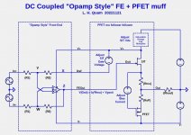
Won’t Y and W be sitting at the SIT offset voltage. So you would have that voltage at your input?
These equations are not the DC state, i.e. assuming the inputs are at ground.Won’t Y and W be sitting at the SIT offset voltage. So you would have that voltage at your input?
Aol is the open-loop gain, Acl is the closed loop gain
x=((Aol+Acl+1)*z)/Aol
y=((Aol+Acl+1)*z)/(Acl*Aol+Aol)
w=z/(Acl+1)
When Aol is infinite:
x=z
w=y=z/(Acl+1)
If Aol is relatively high (over 100), then the DC level of FEout (Z) will follow X.
- Home
- Amplifiers
- Pass Labs
- BAF 2022 SIT AMPS