Im my view, the VFET lottery amps vividly demonstrated that when you use an SIT as a source follower in an output stage, it's tremendously advantageous to connect its drain terminal to GROUND. Because SITs have triode-like characteristics, they have a quite low drain impedance, and any noise / hum / HF / yukk applied to the drain, will find its way to the source -- the amplifier output. The simple solution is to connect the drain to the lowest noise power rail. Which is GROUND.
Mark, clever idea. Most of us have come to take for granted the necessity of the AC ground path formed via the main power supply electrolytic filter caps for power follower stages. It’s always been best not to think much about how clean of a ground that path actually forms. Your suggestion to wire connect the Source/Collector/Plate terminal to ground, and then power the stage from a Neg. Rail, only seems obvious once you’ve seen it.
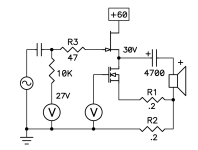
Hi ZM,what's rail, Iq, bulb data?
Shinyfugly!

When the bulb and a series ammeter were the only load on the power supply, the bulb dropped 89V and pulled 2A14, so 41R6, hot.
The voltage at the SIT drain was 30V6.
The voltage across the 2R "source resistor" is 3V5 on start and rising, so Iq of 1A75. I didn't measure the SIT gate directly but by math it thus at -3V5 Vgs.
The 2R power resistor is only a 10W rated little guy and gets scorching hot, quickly so I don't run this thing long. Afterall it's dissipating over 6 watts. I've had the caps on one of these explode out before from heat.
Also I should mention the last time I looked at the ripple on this supply it was awful, like 9V p-p on 90V loaded. I have some ideas why.

This thread has been quiet for a long time, but I would like to report on something I just noticed that was not previously discussed.
In the last circuit shown in Papa's paper "BAF 2022 SIT Amps" (post #1 of this thread), which I have referred to as Papa's NMUFF, the NFET appears to not be an follower, since the NFET gate is driven relative to its source rather than its drain. I suspect that this strongly affects the distortion contributed to the output by the NFET.

In the last circuit shown in Papa's paper "BAF 2022 SIT Amps" (post #1 of this thread), which I have referred to as Papa's NMUFF, the NFET appears to not be an follower, since the NFET gate is driven relative to its source rather than its drain. I suspect that this strongly affects the distortion contributed to the output by the NFET.
You could consider R2 to be a current sensing resistor, because the voltage across R2 includes a term (Loudspeaker_Current * R2). This proportional-to-OutputCurrent voltage is applied to the source of the Nchannel MOSFET. In fact there is a two-resistor voltage divider: the top resistor is R1 and the bottom resistor is (1 / MOSFET_gm). You could consider this to be "feedback" from the output to the input transistor. Go through your own analysis of the circuit and decide whether you think the feedback is negative or positive. Then decide whether you think the feedback affects distortion.
It is the same as a mu-follower connected to the drain with the speaker connection taken from between the CCS setting resistors. It helps keep the current constant over the voltage swing range and lowers distortion. Very clever of Pa. Well, what did you expect?
The resistor R1 serves two functions: 1) It degenerates the NFET, modifying its effective gm, and 2) it is contributed to the total voltage drop across R1+R2 for the bias servo. R1 can be totally eliminated, as I did with my SIT-NMUFF variant, by suitably reducing the value of R2 and reducing the voltage threshold of the biss servo.You could consider R2 to be a current sensing resistor, because the voltage across R2 includes a term (Loudspeaker_Current * R2). This proportional-to-OutputCurrent voltage is applied to the source of the Nchannel MOSFET. In fact there is a two-resistor voltage divider: the top resistor is R1 and the bottom resistor is (1 / MOSFET_gm). You could consider this to be "feedback" from the output to the input transistor. Go through your own analysis of the circuit and decide whether you think the feedback is negative or positive. Then decide whether you think the feedback affects distortion.
Details of my implementation of the SIT/NFET amp are in the "SIT NFET MUFF Mutant Power Amplifier" thread here: https://www.diyaudio.com/community/...ff-mutant-power-amplifier.394943/post-7247023
- Home
- Amplifiers
- Pass Labs
- BAF 2022 SIT AMPS