Decrease the resistor connected to the optocoupler LED or increase the resistor connected to the optocoupler photo-transistor.How to adjust/lower DC bias current with opto bias circuit?
These equations are not the DC state, i.e. assuming the inputs are at ground.
Aol is the open-loop gain, Acl is the closed loop gain
x=((Aol+Acl+1)*z)/Aol
y=((Aol+Acl+1)*z)/(Acl*Aol+Aol)
w=z/(Acl+1)
When Aol is infinite:
x=z
w=y=z/(Acl+1)
If Aol is relatively high (over 100), then the DC level of FEout (Z) will follow X.
Well, thats pure The movie ALIEN mofo bs to me. But i am so slowly coming along 🙂🤚
But keep it up, sooner or later (you) we will have a cool topology well worth testing.
If it purely musically rocks your boat? Well? Could be: It might as well really rock, soul and funk my boat too😎👍
Move your fans: Push instead of pull. Dont frye them if you dont have to.
🙂👍 Peace!
Well? Time to enjoy some of the truely, truely, good sounding amazing music from teh interwebs: Straight out of not at all lossless Youtube.
So? If this ACTUALLY sounds bad to you, you, and you? Something in YOUR setup sucks several gigantic Elephants etire Djungle A**es. The entire friday night long.
To be honest.
Well!? Here it is: Enjoy! 🤗
So? If this ACTUALLY sounds bad to you, you, and you? Something in YOUR setup sucks several gigantic Elephants etire Djungle A**es. The entire friday night long.
To be honest.
Well!? Here it is: Enjoy! 🤗

sound good on AcaMiniWell? Time to enjoy some of the truely, truely, good sounding amazing music from teh interwebs: Straight out of not at all lossless Youtube.
So? If this ACTUALLY sounds bad to you, you, and you? Something in YOUR setup sucks several gigantic Elephants etire Djungle A**es. The entire friday night long.
To be honest.
Well!? Here it is: Enjoy! 🤗
Doesnt work, I had to increase mu-follower source resistors from 2x0.22R to 2x0.33RDecrease the resistor connected to the optocoupler LED or increase the resistor connected to the optocoupler photo-transistor.
I misunderstood your original question. I thought you only needed a minor adjustment to the bias current.Doesnt work, I had to increase mu-follower source resistors from 2x0.22R to 2x0.33R
Yes, you have discovered the major limitation of that optocoupler circuit. Ibias*(R1+R2) mist be approximatly 1.2V.
You can get below 0.3V with a pair of bipolar transistors.You can take that down to about .6v with a bipolar transistor.
Everybody in this thread, take a look at this - Neat!!
https://www.diyaudio.com/community/...ff-and-defisit-amplifier.392733/#post-7187264
https://www.diyaudio.com/community/...ff-and-defisit-amplifier.392733/#post-7187264
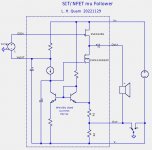
Im my view, the VFET lottery amps vividly demonstrated that when you use an SIT as a source follower in an output stage, it's tremendously advantageous to connect its drain terminal to GROUND. Because SITs have triode-like characteristics, they have a quite low drain impedance, and any noise / hum / HF / yukk applied to the drain, will find its way to the source -- the amplifier output. The simple solution is to connect the drain to the lowest noise power rail. Which is GROUND.
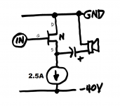
If the SIT is an Nchannel device, that means you're running on a positive ground / negative supply rail system. Not much of a problem unless you accidentally try to use an SMPS whose negative output is permanently connected to Protective Earth. So don't do that. There are plenty of SMPS that don't short VOUT- to Protective Earth, both bricks and open frame boxes. Or if you build a linear supply with a power transformer, you can quite easily connect Protective Earth to a different terminal than VOUT- .
Example diagram below.
_
Attachments
I agree that is the simple solution, which works great with the SIT/PFET mu follower.... The simple solution is to connect the drain to the lowest noise power rail. Which is GROUND. ...
Another solution is to clean up the power supply using a capacitance multiplier, which can be thought of as a form of cascoding in series with the SIT drain. I did this with my SIT-3X amplifier and have no problems with supply noise.
Cap mul requires extra parts and big heatsink, plus it reduces your total available supply voltage (thus your maximum output power). Some people running power MOSFET cap muls report a 4.5 to 5 volt drop from in to out; that would reduce a lottery VFET amplifier's max RMS output power from 20 watts to 15 watts. And what does the cap mul give you in return? The comfort and familiarity of the same old, same old positive supply with negative ground? As Morpheus advises Neo: free your mind.
edit- fixed an arithmetic error
edit- fixed an arithmetic error
Mark's advice about grounding the drain of SIT source followers reminded me that I had not done this with my new 2SK182ES source follower test amp, so I changed the grounding scheme. Because I had done FFT measurements of the amp with the drain at V+, I could compare it now to the grounded drain. I found a definite reduction in noise.
Thank you, Mark, for the reminder.
Thank you, Mark, for the reminder.
Been wanting to try one of the basic BAF 2022 SIT amps for a long time. This one channel with self-bias and a light bulb as current source sounded better to me than it had a right to.


- Home
- Amplifiers
- Pass Labs
- BAF 2022 SIT AMPS