Regarding the negative voltage on the gate (-3V), it is absolutely necessary to control this voltage when playing with normally-on devices or else maximum demolishing current will flow.I bought 4 of the THF-51S parts when the whole "While They Last" thread was first started. Since my DIY skills more or less boil down to being able to solder and follow instructions, I don't really understand the circuits Nelson shared in the PDF. Specifically, can somebody tell me what the things I've noted in these JPEGs taken from the presentation mean? And I for one would be REALLY appreciative if one of the more accomplished members of the forum would actually share a complete circuit, with part specifications, that would make use of the THF-51S parts.
PaulInWA, part of Mr. Pass' 2015 BAF lecture describes an amp similar to #2, but realized using the unobtainium 2sk77B:
Just curious, are these designs in any way related to the design (kit?) around the Tokins that is coming somewhere in the not too distant future? Or will that be a whole other animal?
@Nelson Pass, @Zen Mod, @6L6, @Michael Rothacher: Is there is any significant sonic signature difference of these new topologies with THF-51S compare to Sony VFET from the lottery? (Just trying to prioritize projects 🙂) Thanks you.
Last edited:

A single 300VA toroid like the AN-3236 has a pair of secondaries that output 36VAC each. With each secondary across it's own bridge rectifier and linear filtration you will get ~48VDC, which is a little high for the +40V circuits shown and too low for the +60V circuits, but might work, just at a different operating point that isn't quite in the sweet spot. If you instead wire those secondaries in series, dot-to-no-dot, and put it across a single bridge rectifier, that 72VAC should give +96VDC rectified. Pretty close to 100V.So, i am wondering: Do you HiFi building dudes think it is possible to later also use them 100V powersupply nuggets in the other Pass proposed SIT -topologys?
…With reasonable modifications possible to handle for a happy fairly n00b amp builder like me?🙃
Or is it simply not a good idea at all?
If you think you can get these designs to work reasonably well with 48V or 96V then you can do that with a single trafo.
To get close to 100V, you could do as above but wire the two 48Vdc in series to get 96Vdc, that way you don’t have to use big filtering caps rated at least 100Vdc.
Just an idea.
Just an idea.
Would something like the Super Regulator board in the store be what you could use to provide and "control" the -3V on the gate? I don't suppose you could just stick a battery there for breadboarding the circuit? https://diyaudiostore.com/collections/power-supplies-accessories/products/super-regulatorRegarding the negative voltage on the gate (-3V), it is absolutely necessary to control this voltage when playing with normally-on devices or else maximum demolishing current will flow.
You could use a super regulator but it is over-kill. A trim pot/voltage divider is also needed to adjust the voltage as the -3V shown in the concept schematic is an example only, as the voltage needed will depend on each individual SIT.
A simple regulated supply as shown in Michael Rothacher's L'Amp will suffice:

A simple regulated supply as shown in Michael Rothacher's L'Amp will suffice:

Also check out ra7’s TDV amp thread for some exploration in simple biasing schemes
Thanks. Continuing the trend of just how stupid a question can I figure out to ask, looking at that circuit and reading some of the source material I'm guessing that Michael's choice of a transformer with 40VAC outputs gives you something like 55 VDC after rectification. The circuit Nelson suggested had 100 VDC to a single 300 W light bulb that I think drops the voltage to 18VDC. Michael's circuit seems to use two 300 W bulbs in parallel with ~55 VDC input. Does that also drop the voltage to ~18VDC? A voltage drop calculator I referenced seemed to suggest that, but I was just guessing at the resistance and current draw part of the calculator (https://elecurls.tripod.com/drop-res.htm). But it also seems like different requirements of the 2SK82 versus the THF-51S I would use might account for the difference in design?You could use a super regulator but it is over-kill. A trim pot/voltage divider is also needed to adjust the voltage as the -3V shown in the concept schematic is an example only, as the voltage needed will depend on each individual SIT.
A simple regulated supply as shown in Michael Rothacher's L'Amp will suffice:
View attachment 1102585
Yes, different load lines for 2SK82 and THf-51S chosen by Michael and Nelson.
Some information on load lines (tubes shown but applies to SITs also):
Load Lines
Some information on load lines (tubes shown but applies to SITs also):
Load Lines
This one helped me out a lot
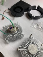
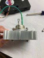
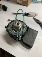
Here's a trash heat sink idea, a CPU cooler bolted to a THF-51S. there's a smol TO-3 mica and goop in between that's hard to see. I don't know what brand/model these CPU coolers are, these were gifted to me by a friend. Eventually I'll try to build an amp with these, but it could be a while.
Attachments
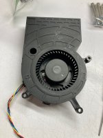
During quiet passages, you can point out the distinct sound of the blow off valve to your friends! 😀
Gpu... grafic card maybe https://www.amazon.it/BAZA1233R2U-chassis-integrated-machine-cooling/dp/B0927CG3VYHere's a trash heat sink idea, a CPU cooler bolted to a THF-51S. there's a smol TO-3 mica and goop in between that's hard to see. I don't know what brand/model these CPU coolers are, these were gifted to me by a friend. Eventually I'll try to build an amp with these, but it could be a while.
This is a great idea and allowed these coolers to have a second life !Here's a trash heat sink idea, a CPU cooler bolted to a THF-51S. there's a smol TO-3 mica and goop in between that's hard to see. I don't know what brand/model these CPU coolers are, these were gifted to me by a friend. Eventually I'll try to build an amp with these, but it could be a while.
- Home
- Amplifiers
- Pass Labs
- BAF 2022 SIT AMPS