It appears while us mere mortals have been sleeping the mad scientist has been sweating away in his laboratory quietly working burning the midnight oil. I was going to say do not tease but tell us what 50 watt Class A SIT mimicking amplifiers sound like but I see that is reserved until 6moons publishes the article.
I'm thinking of using something like this on the supply. Any other suggestions welcome.
Here is one with an added resistor. This allows you to use a higher
value for the RC filter. If you used a higher value in the original the
voltage regulators (in the case of TL431) might not bias up, and if
instead you solve that problem by making C much larger, you might
see some motor-boating on the circuit.
😎
Attachments
@wdecho
I haven't listened to anything yet. Just one bench proto of each to confirm the basics before getting boards ready for the chassis. They're monoblocks, so I won't have enough chassis to listen to them all at once anyway. There's a good bit of work to be done still, so please don't let me distract you. I'm months away. 🙂
I haven't listened to anything yet. Just one bench proto of each to confirm the basics before getting boards ready for the chassis. They're monoblocks, so I won't have enough chassis to listen to them all at once anyway. There's a good bit of work to be done still, so please don't let me distract you. I'm months away. 🙂
Thank you Nelson.Here is one with an added resistor. This allows you to use a higher
value for the RC filter. If you used a higher value in the original the
voltage regulators (in the case of TL431) might not bias up, and if
instead you solve that problem by making C much larger, you might
see some motor-boating on the circuit.
😎
I'll give that one a try.

Sorry to be late in replying - away for the weekend.
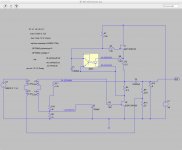
I was able to get the original Schade circuit stable at 1.8 - 2.0 amps
To be make sure it wasn't my wiring I brought up the generg circuit (below) - only required a couple of changes (gate resistors and bias supply).
With voltage at D1 = 50V and D2 = 25V. R2 = .33 ohm and R4 = .5 ohms. Current through these resistors is 1.5A. Rock solid.
I want to build the other channel and give a listen.
I also want to try a IXFN/2SK182 version with 60V supply and then I will try to resolve the IXFN/IXFN version.
Best
Bob
Attachments
Very happy with this power supply circuit. Gives extremely good performance.
Thanks again Nelson.
I doubled up on IRFP240.
I changed over 2 x IRF240 to 2 x IRFP250 per mono supply.
Last edited:
Very happy with this power supply circuit. Gives extremely good performance.
Thanks again Nelson.
I doubled up on IRFP240.
This is interesting! What typical values in the components is there ?
This is interesting! What typical values in the components is there ?
Assuming you have 70V of unregulated dc coming off CRC, and intend on using IRFP240 or 250.
First Diode. 1N4004
Zener Diodes: 6 x 11V (or any other combination that gives you between 64V and 66V)
Top resistor between 1k and 2k to feed Zener network adequate current.
For RCR network at gate of mosfet. I used 220 Ohm 1000uF 220 Ohm. You could also use something like 1kOhm 200uF 1kOhm.
Quite a bit of flexibilty on those values.
Mosfets: whatever you have with decent transconductance. IRFP240 and IRFP250 are good examples. They are also cheap.
Note: If you have less than 65V of unregulated supply voltage coming off CRC you can either accept a lower regulated supply voltage, or alternatively you could try using depletion mode mosfets which will give you a higher regulated supply (around 4V higher) voltage compared with IRFP devices.
Last edited:
Very happy with this power supply circuit. Gives extremely good performance.
Thanks again Nelson.
I built a scaled down version of this supply with an IRF510 to supply 27V at ~50mA, and it does indeed perform very well (as does the little headphone amplifier it is powering)!
I will offer tomorrow seven 2SK180 with data at swap meet with data.
If anyone is interested you can PM me.
If anyone is interested you can PM me.
Bifilar transformer
Is there an obvious reason why I couldn't use a bifilar wound transformer for the BAF schade circuit? I already have a nice JT-11 here.
I can put a LCR meter to it and and look for differences in SPICE.
Thanks
Is there an obvious reason why I couldn't use a bifilar wound transformer for the BAF schade circuit? I already have a nice JT-11 here.
I can put a LCR meter to it and and look for differences in SPICE.
Thanks
Is there an obvious reason why I couldn't use a bifilar wound transformer for the BAF schade circuit? I already have a nice JT-11 here.
I can put a LCR meter to it and and look for differences in SPICE.
Thanks
I dont see any. But i may not be the best reference...
Looking forward to the results from Spice.
Best
@wdecho
I haven't listened to anything yet. Just one bench proto of each to confirm the basics before getting boards ready for the chassis. They're monoblocks, so I won't have enough chassis to listen to them all at once anyway. There's a good bit of work to be done still, so please don't let me distract you. I'm months away. 🙂
any news regarding the status of the work? 🙂 ( forgive me please my impatience, but very interested in this amp ;-) )
2picoDumbs has a thread going for this. I'm out of commission while I find a new place to live 🙂
I'm hoping to have a new kitchen table by late Fall.
I'm hoping to have a new kitchen table by late Fall.
2picoDumbs has a thread going for this. I'm out of commission while I find a new place to live 🙂
I'm hoping to have a new kitchen table by late Fall.
Thanks for the quick reply. I have sent him a PM.
Best wishes for the new place. We are looking forward to having you back with a big kitchen soon again.

- Status
- Not open for further replies.
- Home
- Amplifiers
- Pass Labs
- BAF 2015 Coverage