In my case (the low power versions) the DC op point changes as well with a change of the heat sink temperature, but not dramatically.
I tested that by covering the heatsink for some minutes and i measured a 9% voltage drift at the drain of lower mosfet. Not enough to feel the need for mitigating measures.
But then again, since i use "Genergs" circuit (attachment) there is an interaction of bias supply and current draw of the lower mosfet. More amps through the mosfet result in lower bias voltage (kind of built-in thermistor)
Another possibility regarding temp management of the hockey pucks i keep thinking about is temperature regulated active cooling.
The pucks have a very low J/case coeff, in other words, if i am not mistaken,
if we manage to control the sink temp we have a good chance to control the junction temp.
Attachments
I wonder whether the IRLB3813 is really that much better than the IRFP7430? Can anybody confirm?
The IRLP3034 is better then both. The IRLP3034 is a more powerful TO247 and 40 Volt Vds rating version of the IRLB3813. I have not measured THD, it is just my subjective experience from 30 different single channel alligator-clip-rats-nest test amps I have built and listened to this last two years.
The IRLB3813 is a nice mosfet for low voltage usage like the ACA or any other Pass DIY amp with a powersupply of less then 30 volts (or 2 x 15 volts for DC-coupled amps).
The IRFP7430 is not very linear and nice when it comes to objective measured performance, but it can make anything sound fun and alive. It seems to be able to breath life into a sinewave....
The IRLP3034 is much more linear then the IRFP7430, and can sound very open, vivid and "large" in no feedback single end amplifiers.
It is quite similar to the IRLB3813 in general character but much more powerful and with more of what I want to call "triodity".
Cheers,
Johannes
https://www.infineon.com/dgdl/irlp3034pbf.pdf?fileId=5546d462533600a4015356693edf2656
https://www.infineon.com/dgdl/irl3803vpbf.pdf?fileId=5546d462533600a40153565f92692559
https://www.infineon.com/dgdl/irfp7430pbf.pdf?fileId=5546d462533600a40153562ca5682025
I am very curious on the IRL3803Vpbf.
It seems like a very nice "triody" mosfet with low gate-capacitance.
Cheers,
Johannes
https://www.infineon.com/dgdl/irl3803vpbf.pdf?fileId=5546d462533600a40153565f92692559
https://www.infineon.com/dgdl/irfp7430pbf.pdf?fileId=5546d462533600a40153562ca5682025
I am very curious on the IRL3803Vpbf.
It seems like a very nice "triody" mosfet with low gate-capacitance.
Cheers,
Johannes

Here is the ohmic region of the IRL3803VPbF. It seems quite similar to a SIT or Triode.
Cheers,
Johannes
Circlomanen,
A few novice questions for you...
These are enhancement mode mosfets?
How do you know where to set the drain voltage and current for the circuit, based on the graphs that show the ohmic region?
Could these be dropped in to a Delite type amp circuit to see who they sound?
Could a resistor current sources be used?
The Nemesis articles are useful for this info, but when I see the transformer on the output, it kind of slows down the potential for a quick build.
Thanks,
Vince
You will want to take a close look at the dissipation figures at the higher
voltages 10v - 40v on these parts. They might be very suitable for
cascoding.
voltages 10v - 40v on these parts. They might be very suitable for
cascoding.
You will want to take a close look at the dissipation figures at the higher
voltages 10v - 40v on these parts. They might be very suitable for
cascoding.
That was a bit over my head. But as a guess, did you mean that it would be interesting to exploit their triodish characteristic when cascoded?
To Johannes
Thank you for the hints for different devices. I see more work ahead...

I think it is this graph Nelson Pass refers to.
I would guess that the area of safe operating area is applicable to a mosfet without any source-resistance. I have been running the IRFP7430 with 25 volts Vds and 2 ampere of current without any thermal instability. It is a 366 watt device with a linear derating factor of 2.4 w/C. At 100 degrees Celsius silicon temperature you still have 366 - 100 x 2.4 = 126 watt power capacity left.
These devices can be prone to thermal runaway if there is no or too little source resistance.
Cheers,
Johannes
These are enhancement mode mosfets?
How do you know where to set the drain voltage and current for the circuit, based on the graphs that show the ohmic region?
Yes these devices are enhancement mode. They need 2.5 - 4.5 volts Volts between gate and source to work. You use them in the same way you would use an IRFP150 or IRL540.
They will sound quite different compared to normal Pentodish devices like IRFP240/150/044 etc.... You can tune the character of the device over a very wide area of Voltages and currents. You have to test it yourself in the amp you are building.
It is important to not exceed the maximum Voltage over the device.
Could these be dropped in to a Delite type amp circuit to see who they sound?
Could a resistor current sources be used?
I would not recommend the Delite amp. It has a way to high power-supply Voltage.
It will zap the device.
You can use these devices in almost any other Pass DIY amps, as long as the power-supply Voltage is less then the device max Vds.
I would recommend using a resistor current source since this will help greatly with finding some distortion cancellation together with the Triody transfer-curves.
These devices takes some willingness to experiment. They sound quite different and can give large amounts of distortion if used wrong.
I have a single channel no global feedback amp with an IRFP7430 with a 2 ampere CCS. There is a 0.75 ohm source-resistor as the only feedback mechanism. It has an excessive amount of distortion, but it does not sound anything like a distorting normal Pentodish IRFP150. Even though it has an excessive amount of distortion, it is still a lot of fun to listen to. It can breath life into any speaker and any recording. The problem is that there is still to much "life" where there should be non. It turns Diana Krall into Rammstein, and Eva Cassidy into Lemmy Kilmister. As long as you like Lemmy and Rammstein more then Eva and Diana then this is the amp you want.
With a small amount of global negative feedback to tame the inherent "Lemmy" in the IRFP7430, I guess you can get a very nice sounding amp.
Cheers,
Johannes
Looks like very conservative values for maximum safe DC operation.
Yes.
My experience with these devices is that they are very rugged and tough.
I have run more then 3 ampere and 25 volts through an IRLB3813 for a few seconds.
I hade coupled a small piece of wire directly from the plus rail from the power supply to the drain of the bottom device. I discovered my mistake by the smell of the burnt silicon-pad. I have no idea if the mosfet would have survived for any longer. I cut the power immediately when I discovered my mistake.
The IRFP7430 was run with 25 volts and 2 ampere for many hours. It got to hot to touch, but still works perfect in the new amp.
I think that the safe operating area graph is about thermal runaway. They need some source-resistance for thermal stability when used outside the safe operating area.
Cheers,
Johannes
I wonder if we could use PM45502 in BAF2015:
PM45502C pdf, PM45502C description, PM45502C datasheets, PM45502C view ::: ALLDATASHEET :::
PM45502C pdf, PM45502C description, PM45502C datasheets, PM45502C view ::: ALLDATASHEET :::
Just making a few improvements. Still alive and kicking 🙂
https://vimeo.com/175854740
Thanks for the news cool

Last edited:
I really like that music video.
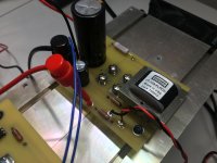
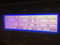
Getting things back up to speed here. I pulled this out of the mothballs today. That's Nelson's BAF 2015 Schade Amp, and yep, that's .04%! 🙂 I was trying out the mu follower tap. 🙂
I'll be working on getting these DIY-ready.
Getting things back up to speed here. I pulled this out of the mothballs today. That's Nelson's BAF 2015 Schade Amp, and yep, that's .04%! 🙂 I was trying out the mu follower tap. 🙂
I'll be working on getting these DIY-ready.
Attachments
Nice Michael! Being that you are the vfet wizard, could you comment briefly on the schade 2015 sound when you are done building? 🙂
Thanks,
Vince
Thanks,
Vince
Still haven't built a proper stereo pair of these. That's what I'm working on now, so I hope to answer that later this summer 🙂
- Status
- Not open for further replies.
- Home
- Amplifiers
- Pass Labs
- BAF 2015 Coverage