I am sorry when I do too much "Cassandra".
I think you gave the decisive hints Mr. Pass to avoid problems. Nevertheless I have the impression that most of us hesitate by the high current (PSU) and heatsink demands.
But this is all speculation.
Happy to hear Mike that your amp came to an end and worked, up to now I will only refer to your success.....:--))
It is my case, that I am waiting for someone to review this amp. Then I decide if it is wort to build, because of massive heat generated and quite low damping factor. But I would definitely use SMPS PSU.
Hopefully in the next month I will try a version of the 2SK77B circuit substituting 2SK182e for the 2SK77B.
Any advice greatly appreciated.😀
Any advice greatly appreciated.😀
Invite some friend, enjoy music, have smome drinks while dancing around Baf 2015 amp ... and have small BBQ party on it 😀Hopefully in the next month I will try a version of the 2SK77B circuit substituting 2SK182e for the 2SK77B.
Any advice greatly appreciated.😀
Nice wk

somebody really needs to gather Nelson's BAF materials from years past and put them in a sticky, or better still, on the FW site. They get harder and harder to locate as time passes... I tried yesterday but gave up.
Bob, like jama says, build it and then I'll bring the steaks to bbq and some tasty Cabernet to wash them down with. 😀
Invite some friend, enjoy music, have smome drinks while dancing around Baf 2015 amp ... and have small BBQ party on it 😀
Nice wk
my two cents
I have built 4 versions of low power Baf Schade amps.
All with B+ 19.3 V and CCS with 1.17A
Motor boating is a problem that needs to addressed and DC coupling worked fine in my case.
I appreciate this design a lot. Good gain and decent DF. Low noise floor and excellent sonic performance.
The mosfet IRLB 3813 has been my preferred device, both for my ears and in LT-Spice where harmonics are up to 15db lower than with other mosfets.
This amp requires a low impedance source to shine. I am perfectly happy with LuminAria driving it.
Building on the gained experience i would do the following if i were to go for the 50W version.
1) not worry about the CCS. I have full faith in this current limiter that will protect the lower mosfet from too much current
2) Use a SMPS to keep the costs down. The CCS shall keep the noise from the supply down
3) Use a thermistor in the bias chain for the lower mosfet. Otherwise it may be difficult to reach and to keep the voltage at the drain of the lower mosfet at a set value.
A change of the ambient temperature of 10 degrees (winter summer) may totally upset the situation.
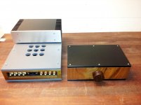
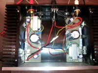
Enclosed are pictures of the small BAF Schade 5W amp in company of LuminAria and a Transformer Volume control.
I have built 4 versions of low power Baf Schade amps.
All with B+ 19.3 V and CCS with 1.17A
Motor boating is a problem that needs to addressed and DC coupling worked fine in my case.
I appreciate this design a lot. Good gain and decent DF. Low noise floor and excellent sonic performance.
The mosfet IRLB 3813 has been my preferred device, both for my ears and in LT-Spice where harmonics are up to 15db lower than with other mosfets.
This amp requires a low impedance source to shine. I am perfectly happy with LuminAria driving it.
Building on the gained experience i would do the following if i were to go for the 50W version.
1) not worry about the CCS. I have full faith in this current limiter that will protect the lower mosfet from too much current
2) Use a SMPS to keep the costs down. The CCS shall keep the noise from the supply down
3) Use a thermistor in the bias chain for the lower mosfet. Otherwise it may be difficult to reach and to keep the voltage at the drain of the lower mosfet at a set value.
A change of the ambient temperature of 10 degrees (winter summer) may totally upset the situation.
Enclosed are pictures of the small BAF Schade 5W amp in company of LuminAria and a Transformer Volume control.
Attachments

Thank you jostwid for this insight in your fine builds.
Why did you decide to make more low power versions?
Why did you decide to make more low power versions?
Why different builds?
Different devices, different performance. Some of us may remember the improvement the Semisouth SJEP120R100 brought over the IRFP240 for the F2 amp. I think anybody could immediately hear it.
I have tried several devices to see whether there was something to it. In Spice there is, and a lot. I could not model the SJEP120R100 because the models i found did not work. If you have one i would be glad to receive it.
Anyway the BAF Schade design is worth a try. And what continues to matter most is the first Watt. I doubt that the 50 Watt version sounds any better than a good 5 Watt version (given appropriate speakers)
One day i may have to build a 50 W just for the fun of it, to see if it is doable (for me)
I used in Spice this one and it worked
*-------------------------------------
* Rev. B1.0 [May 2012]
*-------------------------------------
* SJEP120R100 SPICE Model
*
* SemiSouth Laboratories Inc.
*-------------------------------------
.model SJEP120R100 D G S
.param R=530m ; R_gate
Rg G Gi {R} tc=-3m
Rd D Di 70m tc=8m 10u
Csd S Di 3p
Cgd G Di 43p
Ji Di Gi S SJEP120R100
.model SJEP120R100 njf
+ Vto=1 Beta=10.5 B=1
+ Lambda=2m Vk=2k Alpha=20u
+ Is=1f N=3.4
+ Isr=1n Nr=6.8
+ Cgd=1n Cgs=755p Pb=2.6 M=0.8
+ Kf=100f Af=1
+ VtoTC=-2m BetaTCe=-0.6 Xti=86
.ends SJEP120R100
and I add a .lib too, delete the .txt at the end.
*-------------------------------------
* Rev. B1.0 [May 2012]
*-------------------------------------
* SJEP120R100 SPICE Model
*
* SemiSouth Laboratories Inc.
*-------------------------------------
.model SJEP120R100 D G S
.param R=530m ; R_gate
Rg G Gi {R} tc=-3m
Rd D Di 70m tc=8m 10u
Csd S Di 3p
Cgd G Di 43p
Ji Di Gi S SJEP120R100
.model SJEP120R100 njf
+ Vto=1 Beta=10.5 B=1
+ Lambda=2m Vk=2k Alpha=20u
+ Is=1f N=3.4
+ Isr=1n Nr=6.8
+ Cgd=1n Cgs=755p Pb=2.6 M=0.8
+ Kf=100f Af=1
+ VtoTC=-2m BetaTCe=-0.6 Xti=86
.ends SJEP120R100
and I add a .lib too, delete the .txt at the end.
Attachments
3) Use a thermistor in the bias chain for the lower mosfet. Otherwise it may be difficult to reach and to keep the voltage at the drain of the lower mosfet at a set value.
A change of the ambient temperature of 10 degrees (winter summer) may totally upset the situation.
Shouldn't the CCS lock the bias current down such that it doesn't change much as ambient temp changes ? To keep CCS current stable with temp, one important thing to do is to keep that BJT far away from the heat.
Hello kasey
No matter what the situation, the CCS will try to deliver the set amperage, lets say the 3.2 A.
If the lower mosfet is not conducting, the CCS will not be able to deliver anything.
If the lower mosfet is fully conducting, that means we have almost short circuit condition to ground, the CCS shall limit the current to the 3.2A that is has been set for.
We can look at the lower mosfet as a variable resistor. We must set it to the value so as to reach at about half B+ at the drain of the lower mosfet.
The problem seems to be that this particular mosfet is changing quite a bit its conductance with changing temperature.
With the thermistor we can counteract this behaviour.
The spectral analysis shows about .3%, which is about the same as the
curve w/ ccs I showed above.
In any case, don't get too excited about spice distortion results - the lower
level models are too simple to capture the subtleties and the data sheets
are designed around the needs of switchers, not linear operation.
curve w/ ccs I showed above.
In any case, don't get too excited about spice distortion results - the lower
level models are too simple to capture the subtleties and the data sheets
are designed around the needs of switchers, not linear operation.
Thank you Nelson for the wise words. LT-Spice is a nice toy but as far from the truth as the result of the interaction of imperfect models.
Unfortunately my distortion measurements are not reliable enough. I wonder whether the IRLB3813 is really that much better than the IRFP7430? Can anybody confirm?
Unfortunately my distortion measurements are not reliable enough. I wonder whether the IRLB3813 is really that much better than the IRFP7430? Can anybody confirm?
Thanks - hadn't thought of that. I'll mess around with the sims and have a bit of a think about this..
In your case, did the o/p DC voltage vary a lot (approx how much ?) if you didn't use the thermistor compensation ?
In your case, did the o/p DC voltage vary a lot (approx how much ?) if you didn't use the thermistor compensation ?
Hello kasey
....We must set it to the value so as to reach at about half B+ at the drain of the lower mosfet.
The problem seems to be that this particular mosfet is changing quite a bit its conductance with changing temperature.
With the thermistor we can counteract this behaviour.
- Status
- Not open for further replies.
- Home
- Amplifiers
- Pass Labs
- BAF 2015 Coverage