It works like glue by the way 🙂
Chill.
Congratulation Michael
Always admire your diy smart style with innovate pcb on the hockey puck top
elegance and order delicious to see build.
Thanks for sharing

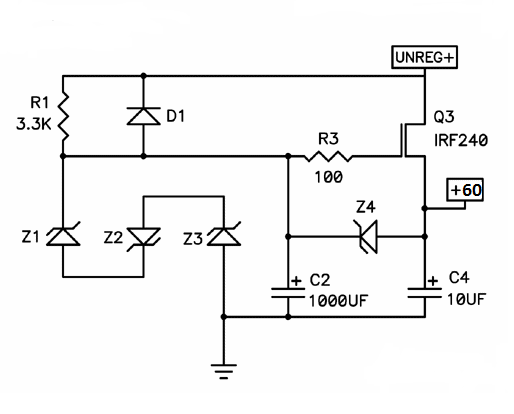
The current for the circuit shown is 3.2 amps, so I don't quite know what
you mean by "current runaway at 2.8 A".
.......
I recall Flocchini experienced problems, but as of 2/10 they seem to have
gone away by themselves.
😎
Thank you Mr Pass for the many hints. I think I did not express correct the "2.8A problem"
I gathered the words of members.....
"Member Jama post 551
The main problem was one CCS that could works to this current and dissipate a lot of power. I have tried some devices, first, IXFN140N20P, but I did not worked for me (broken one mosfet and one THF51
Ci11
Member Ci11* Post 558
1. Power draw is not as expected. I started with +60V, limited to 4A. I measured +26V at the gate of the output device. However, once the output device warmed up, the voltage draw dropped from +60V to about +32V, and the current draw kept trying to push beyond the set limit of 4A. The temperature of the output device was about 160°F. So I increased the current limit to 4.5A, and the result was that it was all quickly "absorbed", with the voltage staying around +32V, current draw at 4.5A, and the temperature of the output device rising to 190°F or so. At this point, I stopped.
Member flocchini also fought hard, maybe he can say some words.
Again I am very happy to have your advices and Mikes working example after these weeks of bad news.
Last edited:
....... Amp test thingamajig........
I like your thingamajigs
they're much neater than my usual whatsthatjinx
I'm thinking of using something like this on the supply. Any other suggestions welcome.
....
besides still needing hefty C4 , why that ?
that's sort of CCS up there , pretty well buffering PSU ripple
of course , reg is welcome if you 're in a middle of winter season
Thank you Mr Pass for the many hints. I think I did not express correct the "2.8 problem"
I gathered the words of members.....
"Member Jama post 551
The main problem was one CCS that could works to this current and dissipate a lot of power. I have tried some devices, first, IXFN140N20P, but I did not worked for me (broken one mosfet and one THF51
Ci11
Member Ci11* Post 558
1. Power draw is not as expected. I started with +60V, limited to 4A. I measured +26V at the gate of the output device. However, once the output device warmed up, the voltage draw dropped from +60V to about +32V, and the current draw kept trying to push beyond the set limit of 4A. The temperature of the output device was about 160°F. So I increased the current limit to 4.5A, and the result was that it was all quickly "absorbed", with the voltage staying around +32V, current draw at 4.5A, and the temperature of the output device rising to 190°F or so. At this point, I stopped.
Member flocchini also fought hard, maybe he can say some words.
Again I am very happy to have your advices and Mikes working example after these weeks of bad news.
My understanding, at least on the optocoupler current source setup, is you have approximately 1.2V across the led (with some fine adjustment) which leads to 1.2V drop across the 2 x 0.2 Ohm resistors (0.4 Ohms) around 3A (ie 3.2A).
If it is wired up correctly it should be rock solid stable.
The only imaginable problem I can possibly see is the bottom mosfet which is set up manually, (highly sensitive to temperature, and very high transconductance), so will need ongoing adjustment till everything reaches thermal equilibrium to get the appropriate voltage at output as shown on schematic.
besides still needing hefty C4 , why that ?
that's sort of CCS up there , pretty well buffering PSU ripple
of course , reg is welcome if you 're in a middle of winter season
Ignore the cap values at output.
I was sure Nelson said somewhere you needed a supply with around 10mV ripple, can't remember exact figure but it was very low.
I can do CRC 512,000uF but I don't think that gets me down to what Nelson suggested at 3.2A.
I don't want to do CLC cause I'm a dumb bastard.
I've built up three versions of the BAF Amp now, the 77B, 182, and the IXFN.
They all work just fine, and I'm a caveman. The plan has been to build the IFFN up into the diyAudio chassis, write them up for 6Moons, and make PCBs available for the store. So, I've been reluctant to jump in and spill the beans. So, that will all be available in time. In the meantime, I can report that it works and you shouldn't be afraid to get on with your own build. If you do run into trouble (which I didn't) the stuff from Nelson a few posts back is about all the troubleshooting info you'll need.
Now, I need a mailing address for these ears. 🙂
Please excuse my lobotomy, but what does IFFN refer to ?
(if not au naturel, I prefer rubber for mating surfaces)
(if not au naturel, I prefer rubber for mating surfaces)
For you, Jacco, I will break radio silence 🙂
IXFN140N20P, AKA the "Schade" amp
IFFN (a typo)
IXFN140N20P, AKA the "Schade" amp
IFFN (a typo)
Last edited:
Great Mike, now I see why you were so quiet......🙂
Some of us were already a bit desperate that there were only small comments to the ugly difficulties CI11 and Jama and other went in.
Again GREAT!
This will be so interesting to build!
And certainly a help for all that already started or simply accompanied like me..... :.)
Gerd
Some of us were already a bit desperate that there were only small comments to the ugly difficulties CI11 and Jama and other went in.
Again GREAT!
This will be so interesting to build!
And certainly a help for all that already started or simply accompanied like me..... :.)
Gerd
It's hard to say what may have gone wrong. These guys are all accomplished builders. Perhaps we'll identify the exact source of trouble in those builds at some point and know what to avoid. Oscillation, motorboating, and (by Grabthar's hammer dare I even say it) inadequate heat removal seem like reasonable suspects. In the meantime, Party On. 🙂
seems Jacco is interested in this build.....
though I do not understand his language.... 🙂
or does he want to warn us from a great danger coming from Mr. Chul?
😀😀
though I do not understand his language.... 🙂
or does he want to warn us from a great danger coming from Mr. Chul?
😀😀
I've built up three versions of the BAF Amp now, the 77B, 182, and the IXFN.
They all work just fine, and I'm a caveman.
The plan has been to build the IFFN up into the diyAudio chassis, write them up for 6Moons, and make PCBs available for the store....
Now, I need a mailing address for these ears. 🙂
Woow Michael that most fantastic & interesting builds.
Could i gently request for videos of 77B, 182, IXFN hockey puck's
i remember one with 180 your diy amp with beauty Françoise Hardy
song on AudioHobby ?


- Status
- Not open for further replies.
- Home
- Amplifiers
- Pass Labs
- BAF 2015 Coverage