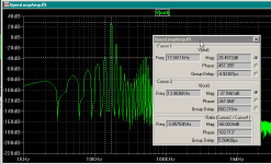
The plot of the output spectrum for the open-loop amplifier is shown below. The difference in marker values (Cursor2 / Cursor1) can be seen as -66 dB.
So now the question becomes "What happens if I do this same test using a feedback amplifier"? If I use the same 1.9A peak current for the interfering signal, what will the ratio of the desired signal at 17 kHz to the dominant third-order intermod product at 14 kHz be? Will it be better or worse than that of the open-loop amplifier?
So now the question becomes "What happens if I do this same test using a feedback amplifier"? If I use the same 1.9A peak current for the interfering signal, what will the ratio of the desired signal at 17 kHz to the dominant third-order intermod product at 14 kHz be? Will it be better or worse than that of the open-loop amplifier?
Attachments
Found it!
If i reduce the stop time, floor will be lower (?) but noisier.
I like more the looks of a clean -170dB floor... 😀
If i reduce the stop time, floor will be lower (?) but noisier.
I like more the looks of a clean -170dB floor... 😀
You're not starting the FFT at t=0 are you? I do my transient from 0 to 2.5 msec, taking the FFT from 1.5 msec to 2.5 msec. If you start at t=0 you get some unwanted transient stuff from the beginning.
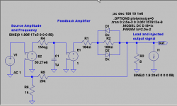
Okay, I put together a model of a feedback amplifier with a nonlinear output impedance. Since there was some speculation that low to moderate amounts of feedback might make the "back EMF" (hehe) problem worse, I decided to pick the gain-bandwidth product to roughly match the Leach amp, which is a very modest 8 MHz. This means for a gain of 21 that the unity loop gain frequency will be roughly 8 MHz / 21 = 381 kHz. That's a very conservative design. This gives about 25.6 dB of feedback at 20 kHz. The model is shown below. I gave it an open-loop bandwidth of 1 radian per second (horrors, that's less than 1/6 of 1 Hz!) and a DC open-loop gain of 50.27e6 or 154 dB.
The schematic is shown below.
The schematic is shown below.
Attachments
You can see the output spectrum in the graph below. The output voltage at 17 kHz is the same (40 Volts peak) and the amplitude of the interfering signal is the same. But what has happened? The third order intermod at 14 kHz, which was 66 dB down from the main signal at 17 kHz in the amplifier without feedback is now 94.6 dB down for the amplifier with feedback!
Chalk another one up to the evils of negative feedback
Chalk another one up to the evils of negative feedback
Attachments

You beat me to it!
I was working with your model - that BTW is the most distorted output stage ever designed 😀 and a more real triple follower output stage.
With the triple, using 2Khz (a freq the ear is very sensitive) and 50Hz (a likelly ressonant freq, where a driver would have most of it's energy - and back EMF should be maximum), sidebands are -110dB...
As you've said, if back emf is a problem is because the designer did a lousy job...
There's lots more investigation that can be done. Such things as output inductors, etc. could be looked at. Hopefully this will stir up some more discussion on the subject. I'd have to conclude that the claims about "back EMF" that we've heard repeated over and over so many times are nothing but a bunch of unsupported assertions.
Of course, if someone wants to support those assertions with something besides more assertions, I'd be very interested to see the results.
I'll talk to y'all tomorrow evening!
Of course, if someone wants to support those assertions with something besides more assertions, I'd be very interested to see the results.
I'll talk to y'all tomorrow evening!
And just a note - did someone ever heard of a speaker able to drive 1.9A INTO the amplifier?
😀 😀
😀 😀
since you guys know so much about this issue
does any of your amps have a solution to it other
than varying the nfb factor, cause you guys sound very
convincing about solving this problem, a schematic showing
a solution would be a real contibution to those you
think are pseudo-scientists and have known about this
spurious nonlinearities of drivers for years
kind regards
mauropenasa said:
Hi All,
I continue to ask the critical "seniors" members, in the comparisons of this matters, of lists me the "truthes" problems to resolve and as resolve them, but lowers always the silence...
Ciao, Mauro
I'm just an old EE - from the time there were only tubes...
Your findings are very important, but I really think they are not related to back EMF.
As you like to experiment, take a driver (a large woofer would be very good), place it in close contact with a speaker playing fairly loud, and measure voice coil generated voltage. This is the back EMF value...
Now, what you are finding are non linearities in speaker impedance, and this factor is very important and deserve to be taken in acount in amplifier design.
Jorge
Raking up some related issues....................
Let me rake up some related issues . Many people do not like the term tight bass . So lets just say "quality of bass reproduction" and refer it to some real equipment so that those who can hear them can figure out more accurately what is being discussed.
Some reviewers talk of "the amp having good control over the speaker ... resulting in 'tight' bass". I assume they meant very high damping factor .
However in many practical systems the lowest impedance in line with the motor circuit of the voice coil we have cable resistance and coil dc resistance ..say 0.1 ohms ( forward and return line ) and 3.5 ohms minimum. So there is 3.6 ohms already. So to make an audible difference the out impedance must be significantly comparable to this.....Zo=0.36 ohms ? To keep things simpler we assume a speaker impedance that is flat over the operating bandwidth.
I've heard a Prima Luna Prologue II and a Creek5350SE at one location and their bass performace is worlds apart . Why ? Does anyone have an explanation ? As explained above super low Zo couldn't possibly be the difference. In any case both amps have low Zout with the Creek probably beating the Prima Luna easily but sounding inferior!
Cheers.
mastertech said:
spurious nonlinearities of drivers
Ah, now you've arrived at the right conclusion.
Speakers are not linear due to the movement of a coil inside an iron pole piece - but not because they generate significant EMF, but because the inductance/losses change with excursion, frequency!
The only known way to do it is current feeding a speaker (real, not just a higher Zo amp) - but then there will be a lot of unwanted secondary effects, and only up to some 3KHz.
see:
http://www.essex.ac.uk/ese/research...J12 Distortion reduction MC current drive.pdf
So, as I've posted before, a bi-ampli sytem, one dedicated (and correctly designed) amp driving a LF/MF speaker in a correctly designed enclosure that takes in account the current drive, or as is suggested in the paper above motional feedback (feedback 😱 ) and another one, conventional design driving the tweeter with active XO would be a very nice combo.
BTW, at least Philips did a similar system in the 70's (and others before that), but I believe that since Philips used too small a woofer it did not succed.
ashok
When one designs a speaker to have 'tight bass' it usually means a Qts of about .5.
The voice coil resistence has already been taken in account to arrive at this value.
So, for your 3.5 ohms vc resistence, one has to add just the cable and amp Zo values, about 0.1~0.5 ohms with usual equipment.
That's a low value, and would change bass response very little.
To make a significant difference, the total cable+Zo should be comparable to the vc resistence.
Why then bass is different between amps? I would look at power supply (expensive components, place to reduce cost - and increase profits), output topology (cheap components, so a lousy design if it's due to it), current capability (some - but not much savings nowadays).
These are the main reasons for better/worse bass quality on my opinion.
Mr jorge
"
When one designs a speaker to have 'tight bass' it usually means a Qts of about .5.
The voice coil resistence has already been taken in account to arrive at this value.
"
you cant just say a qts of 0.5 will give tight bass as this is
only a parameter amongst many and you also dont make mention
of type of loudspeaker system
kind regards
"
When one designs a speaker to have 'tight bass' it usually means a Qts of about .5.
The voice coil resistence has already been taken in account to arrive at this value.
"
you cant just say a qts of 0.5 will give tight bass as this is
only a parameter amongst many and you also dont make mention
of type of loudspeaker system
kind regards
mastertech
I agree. I did not specify the type of system - in my head only closed boxes can give tight bass (just my opinion - not universal truth).
But then, in a closed box system, Qts of circa 0.5 (combination of speaker and box volume) will give tighter bass, while a Qts of 0.707 will give a better extension, but bass will not be so tight - again, my opinion.
Hi Jan,
Your affirmations are corrected, in fact to times have the feeling of have contributed to "create a monster" called "Back_EMF".
My interest to the problems of amp-spk interface is genuine, but it stands to reason that in the forum they stretches to exaggerate with the terminologies. I often forget that not all the frequent visitor to this forum "works" with the electronics, and that of amplify the problem to understand the best is a "professional warpage" ( but I am in good company )🙂
Ciao
Mauro
Gripes
My main gripe about 'Back EMF' is not semantics.
Say someone shouts 'lookout at your left' and the danger is at your right?
The warning is completelly useless...
When one states 'Back EMF' it implies a speaker generated current driving the amplifier, and I believe this thread has shown it not to be significant, but cures would be how to make the amplifier insensitive to it, since it is supposedly an intrinsec speaker property.
Due to it, myths were created as the effect of one channel acoustic output on the other channel due the feedback path, etc.
Now, if one states 'distortions due to speaker non linear impedance', one will look at how to reduce them - this would be the correct approach.
Originally posted by Jorge
Your findings are very important, but I really think they are not related to back EMF.
Now, what you are finding are non linearities in speaker impedance, and this factor is very important and deserve to be taken in acount in amplifier design.
Ciao Jorge,
point 1:
you and Andy_c are 2 " simulator machine " do a big work of analysis, and contribute to give a lot of answers. When make a report on me the "silent seniors" and to the "true problems" not make a report on me that as you but to anyone criticizes without bring any contribute.
point 2:
In my recent post in the thread of lumanauw I have looked for to clarify the reasons of my (recent) test and believe that are sufficiently clear.
Even in connection with the measure of the Back_EMF "true or false" have exposed my thought in that Thread. A serious problem of not comprehension is the fact that they stretches to forget that the models as that of Rodolfo (optimize) simulate only the "linear" conditions of the spk, and in the detail it doesn't exist the magnetic iterations among the Le and the RLC group that simulates the mechanical load, and the thermal variations on Re ( that provoke of the current variations and then of magnetic flux ).
The complete system absorbs, emitted and distorts the mechanical original back_EMF, and to the output clamps you finds an only back_EMF, that it is a real mirror of the sum of all the not-linearity of the system.
The mathematical explanations finds it in the documents ( UnixMan and your link ), in the site of mathematical analysis that I have pointed out , and even in the theories of analysis quotes from Rodolfo: Finite Element Method, used by KEF to simulate the THD produced from a magnetic group.
The signal that finds is the primary sub-judice of the impedance of the spk, it is a variation of voltage if uses a current driver, a variation of current if uses a voltage driver (with varius variations...) .
If you uses a FFT are able even measures the internal thd, that am a lot of high in the points of resonance, and they have similar values to that measurable with a microphone.
From the point of view of the analysis of a "pure" amp the Rodolfo model is perfectly in degree to create conditions of analogous "stress" to that realities, because produces of the Back_EMF "similar" in ampleness to that realities, So sometime I use a similar load for various real test...
Ciao
Mauro
mauropenasa said:
.....and distorts the mechanical original back_EMF, and to the output clamps you finds an only back_EMF, that it is a real mirror of the sum of all the not-linearity of the system. ......
Mauro:
I believe we are narrowing on the real issues now.
1. For the linear case, I hope now both pros and not agree the "back EMF" is a non-issue, but simply the circuit expression of an hybrid electrical and mechanical system.
2. For those of us who trust driver voltage is the variable to correlate with sound pressure, low output impedance is paramount to both achieve desired cone control and to short-circuit / damp unwanted nonlinear voltage components resulting from the electromechanical assembly. Current will reflect the nonlinear behavior but results irrelevant from this point of view, since it does not contribute to acoustics. The relevance in any case is in the proper output stage design to cope with it, what is nothing more than an effective low amplifier output impedance.
3. For those who have reasons to believe the acoustic driving variable is current, just the opposite is true. In this case - differently from the case of voltage drive - it is possible to attain complete current control independently of voice coil variations in resistance and inductance. The resultant driver voltage will exhibit distortion due to driver nonlinearity, but it does not contribute to sound pressure (under the assumption current is the control variable), so the amplifier only must show as near infinite as practical output impedance.
4. Lastly, driver nonlinearity must be also properly placed in perspective. I was mildly shocked with the Le, Re and Bl plots as a function of cone displacement as shown in previous links and the Hawksford paper. But then it must be remembered that above a few hundred Hz cone displacement is just fractions of a mm even for high power output. Driver nonlinearity is a serious issue for low frequency, but largely a milder one above. There is an interesting page I think by Bombardon (will search for the link) where actual distortion measurements are presented for various high end drivers both woofers and tweeters.
Rodolfo
Edit: It is not Re but Cms which varies with displacement, Re varies with temperature.
- Status
- Not open for further replies.
- Home
- Amplifiers
- Solid State
- Back EMF - some considerations