Testing transient back EMF
I suppose it is hard to test an amp with a transient back EMF of a loudspeaker. I mean using test signals.
However it is possible to look at tone burst signals at low frequencies at say 40 Hz or so with speakers connected. Maybe measuring the power supply line current will show exactly what is happening at the point when the signal goes to zero.
Has anyone compared amps with a test like this and correlated it to the bass performance? Find any difference between amps that have tight bass and floppy or indistinct bass ?
Let's just suppose:
There is such a thing as a perfect voltage amplifier.
Now, to decide if a zero output impedance amplifier is better/worse than a higher output impedance amplifier, we place a high quality switch so one can add a resistor in series with the output, at the same time that input level would be adjusted to compensate exactly for the resistor loss.
Let's listen in the same wide band speaker.
Will there be any difference?
Absolutelly.
Both bass and highs will be affected by the lower damping, due to a higher Qts in bass and higher speaker impedance in the highs.
Is this somehow related to the amp qualities/distortion?
No, it's just the expected behaviour of a speaker when driven by a higher impedance source...
That's why listening tests have very little meaning to furnish data for analysis.
What is the mechanism.............
Is damping a passive factor , meaning independant of the speaker and behaves just like a low resistance in parallel with the speaker OR is it active and generates a negative restoring force ( voltage/current) depending on the magnitude of the back emf. If so it must be affected by the complex impedance of the speaker and the magnet / coil structure. High efficiency speakers producing much more back emf and wide band single driver speakers being easier to damp (?).
Any thoughts on this ?
Your question seems much about semantics, although I haven't heard about such division of damping imedance (active or passive). Probaly most silly (but true) asnwer is: it is active by definition of an amplifier. Every transistor is a voltage controlled current source, even in emitter follower mode it is current source made a voltage source by huge emitter feedback.
However a common SS ampifier is not well compared to a series resitor, but rather to a series resistor+inductor because of frequency compensation inside. Probably one could say, that SE triode 0FB is "more passive" effect and high feedback common emitter output is more "active". But I suggest not asking such questions as they are not very scientific and it is unclear where are they intended to lead?
They will just make sceptics (or as they call themselves scientists) laugh and criticise. Better to fight fire with fire I think.
best regards
Re: What is the mechanism.............
Damping factor is the ratio between speaker voice coil resistence divided by the amplifier output impedance.
In almost all amps, t's neve 'real' in the sense there is not a component to be the amp output impedance - it is a result of the circuit implementation.
From a strict amp viewpoint, the amp couldn't care less about its output impedance. It is the speaker that is designed to work with a given range of damping factors, in almost all cases over 10 (or ampifier output impedance 1/10 or less of speaker voice coil resistence).
ashok said:Is damping a passive factor , meaning independant of the speaker and behaves just like a low resistance in parallel with the speaker
Damping factor is the ratio between speaker voice coil resistence divided by the amplifier output impedance.
In almost all amps, t's neve 'real' in the sense there is not a component to be the amp output impedance - it is a result of the circuit implementation.
From a strict amp viewpoint, the amp couldn't care less about its output impedance. It is the speaker that is designed to work with a given range of damping factors, in almost all cases over 10 (or ampifier output impedance 1/10 or less of speaker voice coil resistence).
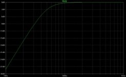
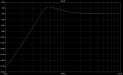
And here's the response of the same speaker when connected to a low damping (1) amplifier.
This change in response can be made just by adding a resistor in series with the amp.
Sound will be fuller, bass will be a somewhat boomy. If the speaker lacked bass, this can sound as an improvemet.
But it's not due to any special quality of the low damping amp - it's just because it has low damping by design.
Attachments
ChocoHolic said:[snip]And most difficult (!): Proper frequency compensation
at any crazy load....
Indeed! I have no formal education at that level (the only poles I know are tent-poles for the campground..), so this is also my bottle-neck.
Jan Didden
Graham Maynard said:[snip] and effects due to a suddenly starting sinewave, though it is essential we do understand the genuine existence of these too, and not claim they go against established theory.[snip]Cheers ........... Graham.
Graham,
Suddenly starting sine waves don't go against theory - they go against practise.
Jan Didden
mauropenasa said:[snip]In this Thread read the comments of "pseudo-intellectuals" that explains that this problems have already be essays a lot of years will do ( is true, but the technologies evolve and the problems stay ), hypothesizes an improper use of the technical term, and the is been ironical about the opportunity to discuss this matters " at street level ". I believe that anyone goes into this deduces technician has an enough base to analyse it. Offend the intellectuals abilities of the members are not synonymous of brain power, and it is the only thing " street level" " that there is in the forum.
Ciao
Mauro
Mauro, indeed technologies evolve, but as you say, the problems stay but also the solutions stay. We can for instance develop a speaker with less non-linearity, that problem gets smaller, but you still have to provide adequate damping to control the motion, and those solutions don't change. I think some members here are somewhat frustrated by this and try to 'force' solutions that intuitively sound good, but are not.
As for offending, what is more offending, trying to explain at a clear and low, non-complex level, or trying to dazzle the audience with new terms, un-understandable long strings of existing terms, even if you know that what you say is unsubstantiated?
Jan Didden
Re: What is the mechanism.............
Damping, in its original form, is the extraction of energy from the vibrating system, so that the system will come to rest. There are always damping factors, otherwise a speaker would continue to sound indefinetely after it was excited, but you can add damping by shorting the speaker. The current that will circulate is converted to heat and that is the energy extracted from the system that damps it.
A zero Zout amp is not a real short, it is an active device that attemps to keep the Vout at zero and does this by gulping up any current the speaker throws at it. As such the Zout is a complex 'thing'. (Sorry for this 'street level' talk 😉 )
Jan Didden
ashok said:Is damping a passive factor , meaning independant of the speaker and behaves just like a low resistance in parallel with the speaker OR is it active and generates a negative restoring force ( voltage/current) depending on the magnitude of the back emf. If so it must be affected by the complex impedance of the speaker and the magnet / coil structure. High efficiency speakers producing much more back emf and wide band single driver speakers being easier to damp (?).
Any thoughts on this ?
Damping, in its original form, is the extraction of energy from the vibrating system, so that the system will come to rest. There are always damping factors, otherwise a speaker would continue to sound indefinetely after it was excited, but you can add damping by shorting the speaker. The current that will circulate is converted to heat and that is the energy extracted from the system that damps it.
A zero Zout amp is not a real short, it is an active device that attemps to keep the Vout at zero and does this by gulping up any current the speaker throws at it. As such the Zout is a complex 'thing'. (Sorry for this 'street level' talk 😉 )
Jan Didden
Hi all,
Back in the first post of this thread, Jorge introduced a model for showing how internal signals of the amp would be affected by introducing the so-called "back EMF" signal driving the amp's output.
One of the concerns that came up was that Jorge's model is purely linear. It would be nice to be able to simulate in SPICE what Hiraga was doing with some of his intermod tests, as well as what Mauro has been doing on the bench too. Back in the "many faces of distortion" thread, one of the things that was discussed was the nonlinear output impedance of a class AB amplifier. It occurred to me that if a one-port behavioral model for this nonlinear impedance could be created, the Zo component in Jorge's model of Post #1 could be replaced by the nonlinear model. Then, the "interface distortion" (to use Otala's term) could be computed and the effects of feedback could be studied in a controlled way. For instance, we could get graphs just like Hiraga's.
I've been playing around with using polynomial controlled sources with the polynomial coefficients set to a "best fit" of the modeled SPICE V/I curve at the EF output. These experiments have been unsuccessful, as the models have a bunch of "wiggles" in the I/V characteristic that aren't present in the simulated data using transistor models. For the optimized bias current case, the output Z vs current has a pretty complex shape, with a hump on both sides of zero output current. However, it occurred to me that the condition of slight underbias, which has only a single hump in the middle, could be modeled behaviorally in a pretty simple way.
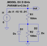
I've attached a picture of a model I've created to do this below. It consists of R1, R2, D1 and D2. The current source is there to test the impedance vs current so I could match it as closely as possible to some other simulated data of a complementary EF. This EF had two each paralleled NPN and PNP output devices. Emitter resistors were 0.22 Ohm, and there was a small source resistor to simulate the non-zero output impedance of the drivers. The circuit was slightly underbiased. I had to crreate my own diode model Dx, with an Is of 20 mA (!) to make the impedance vs current curves agree with the EF simulations.
By replacing Jorge's Zo with this model, we could have a circuit that has distortion, and that distortion would consist entirely of the interaction of the nonlinear output impedance of the amplifier with its load. IOW, all of its distortion would be interface distortion. In that way, investigating the effect of feedback on distortion is equivalent to investigating the effect of feedback on interface distortion.
That's the first half of the proposed analysis. The second half deals with how to get LTSpice to do IM tests without having the problem of DFT leakage (spurious frequency components). That's the topic of the next post.
Back in the first post of this thread, Jorge introduced a model for showing how internal signals of the amp would be affected by introducing the so-called "back EMF" signal driving the amp's output.
One of the concerns that came up was that Jorge's model is purely linear. It would be nice to be able to simulate in SPICE what Hiraga was doing with some of his intermod tests, as well as what Mauro has been doing on the bench too. Back in the "many faces of distortion" thread, one of the things that was discussed was the nonlinear output impedance of a class AB amplifier. It occurred to me that if a one-port behavioral model for this nonlinear impedance could be created, the Zo component in Jorge's model of Post #1 could be replaced by the nonlinear model. Then, the "interface distortion" (to use Otala's term) could be computed and the effects of feedback could be studied in a controlled way. For instance, we could get graphs just like Hiraga's.
I've been playing around with using polynomial controlled sources with the polynomial coefficients set to a "best fit" of the modeled SPICE V/I curve at the EF output. These experiments have been unsuccessful, as the models have a bunch of "wiggles" in the I/V characteristic that aren't present in the simulated data using transistor models. For the optimized bias current case, the output Z vs current has a pretty complex shape, with a hump on both sides of zero output current. However, it occurred to me that the condition of slight underbias, which has only a single hump in the middle, could be modeled behaviorally in a pretty simple way.
I've attached a picture of a model I've created to do this below. It consists of R1, R2, D1 and D2. The current source is there to test the impedance vs current so I could match it as closely as possible to some other simulated data of a complementary EF. This EF had two each paralleled NPN and PNP output devices. Emitter resistors were 0.22 Ohm, and there was a small source resistor to simulate the non-zero output impedance of the drivers. The circuit was slightly underbiased. I had to crreate my own diode model Dx, with an Is of 20 mA (!) to make the impedance vs current curves agree with the EF simulations.
By replacing Jorge's Zo with this model, we could have a circuit that has distortion, and that distortion would consist entirely of the interaction of the nonlinear output impedance of the amplifier with its load. IOW, all of its distortion would be interface distortion. In that way, investigating the effect of feedback on distortion is equivalent to investigating the effect of feedback on interface distortion.
That's the first half of the proposed analysis. The second half deals with how to get LTSpice to do IM tests without having the problem of DFT leakage (spurious frequency components). That's the topic of the next post.
Attachments
For a while now, I've noticed that jcx has been doing intermod simulations with LTSpice. Until yesterday, I haven't been able to figure out how he did it without getting all kinds of spurious frequency components in the FFT. The answer turns out to be pretty simple. It all comes down to figuring out the answers to the following two questions:
1) Is the sum of the two input signals, which have different frequencies, a periodic signal?
2) If so, what's its period?
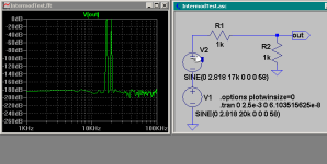
The answer turns out to be so simple I'm embarassed I didn't see it earlier. A signal with period T is also periodic with period N*T, where N is an integer. The attached picture shows a 17 kHz signal plus a 20 kHz signal. If we take N = 20 for the 20 kHz signal, we find that it's also periodic with period (1/(1 kHz)). If we take N=17 for the 17 kHz signal, we also find it to be periodic with period (1/(1 kHz)). Our combined signal therefore must be periodic with period 1 msec. So all we have to do is take a sample period that's an integer multiple of 1 msec to do the FFT. I also picked a time step that's the period of the 20 kHz sine wave divided by 16384 (the default number of FFT samples) but I'm not sure this is necessary. No windowing was used.
The results are shown below. Notice that the residual distortion and noise are 180 dB down. Not too bad! I suspect that jcx may have a better way of doing this, but it looks good enough for now.
1) Is the sum of the two input signals, which have different frequencies, a periodic signal?
2) If so, what's its period?
The answer turns out to be so simple I'm embarassed I didn't see it earlier. A signal with period T is also periodic with period N*T, where N is an integer. The attached picture shows a 17 kHz signal plus a 20 kHz signal. If we take N = 20 for the 20 kHz signal, we find that it's also periodic with period (1/(1 kHz)). If we take N=17 for the 17 kHz signal, we also find it to be periodic with period (1/(1 kHz)). Our combined signal therefore must be periodic with period 1 msec. So all we have to do is take a sample period that's an integer multiple of 1 msec to do the FFT. I also picked a time step that's the period of the 20 kHz sine wave divided by 16384 (the default number of FFT samples) but I'm not sure this is necessary. No windowing was used.
The results are shown below. Notice that the residual distortion and noise are 180 dB down. Not too bad! I suspect that jcx may have a better way of doing this, but it looks good enough for now.
Attachments
Hello, Andy
Very nice!
Thanks for your help.
I'm already changing the circuit to use your model.
Jorge
Very nice!
Thanks for your help.
I'm already changing the circuit to use your model.
Jorge
andy_c said:For a while now, I've noticed that jcx has been doing intermod simulations with LTSpice. Until yesterday, I haven't been able to figure out how he did it without getting all kinds of spurious frequency components in the FFT.
Andy
You're right in that the best is to have an even number of cycles (t=n*1/f)
The shorter the step, the better - I use at least 1000 steps (50n for 20KHz), more is better. It doesn't have to be a submultple of the freq.
Besides, it's very important to go to Tools/Control Panel/Compression and disable compression.
Now, my LTspice doesn't likes me...All I can get is -160dB from it! 🙁
Hi Jorge,
Did you put the directive:
.OPTIONS plotwinsize=0
in your project (using 'S' key to add SPICE directive)?
That turns waveform compression off and improves FFT spurious output performance.
Did you put the directive:
.OPTIONS plotwinsize=0
in your project (using 'S' key to add SPICE directive)?
That turns waveform compression off and improves FFT spurious output performance.
Hello, Andy
No, I've never used this option before. Thanks for the clue.
But it still doesn't likes me!
No, I've never used this option before. Thanks for the clue.
But it still doesn't likes me!
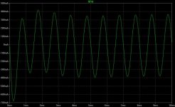
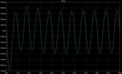
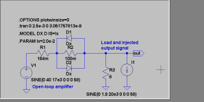
I've been playing around with this, simulating an open-loop amplifier. The picture below shows the circuit configuration. The open-loop amp is simulated as a simple sine wave voltage source with the nonlinear output impedance in series with it.
The output voltage is 40 Volts peak at 17 kHz, with an 8 Ohm load, or close to 100 W. An interfering "back EMF" (ha ha) signal is placed at the output, of frequency 20 kHz. When doing the FFT of the output, the frequencies of 17 kHz and 20 kHz will be seen, but there will also be intermodulation products at 14 kHz, 11 kHz, 8 kHz, 23 kHz, 26 kHz, 29 kHz, etc. The one with the largest amplitude will be the primary third-order component at 14 kHz. What I'd like to do is find the amplitude of the interfering current such that the 14 kHz third-order distortion component is 66 dB below the desired output at 17 kHz (0.05 percent distortion for this component).
This value turns out to be 1.9A peak. Note: I tried going up to -60dB, or 0.1 percent distortion, but it took huge currents. Over 10A and I still didn't get there. Anyhow, the schematic is shown below. Jorge, you should be able to see all my options and time step as well. The time step is the period of the 20 kHz signal divided by 16384.
Attachments
- Status
- Not open for further replies.
- Home
- Amplifiers
- Solid State
- Back EMF - some considerations