Since the level is so high, it would be useful to know the
impedance curve of the speaker and the output impedance
of the amplifier in an effort to distinguish speaker from
amplifier distortion.
impedance curve of the speaker and the output impedance
of the amplifier in an effort to distinguish speaker from
amplifier distortion.
Some data
Here we have 2 hypothetical high feedback amps, opamp based (SPICE models).
Both are stable under capacitive loads, have less than 0.005 % THD at 1Khz, comparable feedback factors, comparable open loop BW, same output power and gain.
A 0.22 ohms resistor was added in series with the output inductor.
The first is a refined project, using a triple/CFP output topology, very low output impedance (VERY high damping)
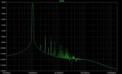
The second is a less refined design, output is just a CFP but signal is taken from the collectors (so more like a transconductance amp).
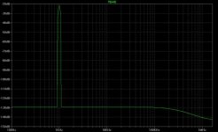
To both a 1kHz, 5V peak signal was applied in series with the 8 ohms load resistor and Interface distortion was measured at the output..
Here's distortion for the triple output amp:
Here we have 2 hypothetical high feedback amps, opamp based (SPICE models).
Both are stable under capacitive loads, have less than 0.005 % THD at 1Khz, comparable feedback factors, comparable open loop BW, same output power and gain.
A 0.22 ohms resistor was added in series with the output inductor.
The first is a refined project, using a triple/CFP output topology, very low output impedance (VERY high damping)
The second is a less refined design, output is just a CFP but signal is taken from the collectors (so more like a transconductance amp).
To both a 1kHz, 5V peak signal was applied in series with the 8 ohms load resistor and Interface distortion was measured at the output..
Here's distortion for the triple output amp:
Attachments
darkfenriz said:But the point is most amps are tested on resistive load with steady state sine. And we really need to analyse what's going on in reality.
regards
Hi Darkfenriz,
I think this is not true in case of professional amps, because if they were to be tested only resistively then their lives surely end up in the field and they are good only upto home use. Infact pro-amps are subjected to much hard stressed reactive loads in order to ensure they well being while operating in real field environments...
regards,
K a n w a r
Glad to hear this.
Do you have any information about such 'performance' tests
I would like to know how IM firures at reactive loads are? Do they go up?
Do you have any information about such 'performance' tests
I would like to know how IM firures at reactive loads are? Do they go up?
Darkefenriz,
he is just shining with his "knowledge" for us so we will start to seek the new Shiva from Mr Kanwar, but so far he don't cheer so much(thinking especially with an attached schematic here on DIYaudio).
I think he's got "rabbit trousers" and is afraid he's schematic will reveal the real level of kanwars Nirvana! 😉
No offense my friends, I really like Tandori chicken!
Best regards,
Michael
..............I really like Tandori chicken..........
Home made or restaurant variety ?
Try "Sharwood Tandoori masala " available in London and I guess Europe . Made here but not available here ! Probably one of the best off the shelf tandori masala powders I have tried. Not too hot either.
Cheers.
darkfenriz said:Glad to hear this.
Do you have any information about such 'performance' tests
I would like to know how IM firures at reactive loads are? Do they go up?
Hi Darkfenriz,
Yeah sure i have some the most important performance tests .
1. The opencircuit test which consists of no load connected at out put and checking for the cross-conduction at frequencies above 20KHZ upto 338KHZ.
2. The RF antennae test- connecting the output of amplifiers with long thin wires upto 25 meters to the load[speakers] and checking the output for any type of RF interference or build up...
3. Connecting the output to LC filter[680uH inductor + 4.7uFd Capacitor] and cranking the amp upto clipping [1KHZ sinewave +50KHZ squarewave input]and checking the output for oscillations and spikes and also determining the worst case dissipiation levels ..
4. Overdriving the amplifier input upto 22dBu and checking any occurance of component malfunction or failure... ie. hardclipping the amplifier and checking the output for any oscillations and spikes if any.
5. Shorting the outputs of amplifiers directly to perform a check on the well functioning of overcurrent protection circuitry..when high voltge transient spikes are generated across the Drain to Source terminals of mosfets...
Ultima Thule said:Darkefenriz,
he is just shining with his "knowledge" for us so we will start to seek the new Shiva from Mr Kanwar, but so far he don't cheer so much(thinking especially with an attached schematic here on DIYaudio).
I think he's got "rabbit trousers" and is afraid he's schematic will reveal the real level of kanwars Nirvana! 😉
No offense my friends, I really like Tandori chicken!
Best regards,
Michael
Hello Michael thanx for the generosity you have showed to us...
regarding rabbit trousers these are best suited to you ..[a perfect fit for you]and not us. As far as schematic is concerened that is our commercial property and publishing here would be an offence in our view...
If you really like tandori chicken, then why not come to us in India and have a great dinner with us.....
best regards,
K a n w a r
- Status
- Not open for further replies.
- Home
- Amplifiers
- Solid State
- Back EMF - some considerations