There is a lot of arguments going on at the forum re the influence of back EMF.
Just to give some perspective to beginners, here is a simulation, using as a load a real speaker model (also posted in the forum):
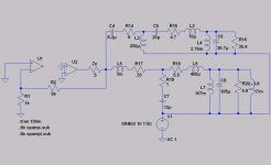
U1 is a high gain voltage stage (gain = 10K, BW = 30MHz) like the input section of an amp, U2 is an unity voltage/high current gain stage, like a triple EF output.
Zo is the open loop output impedance of U2.
The components to the right of Zo model the speaker, to which a 10V peak (possibly a very high value) back EMF is apllied at 110 Hz, where the speaker is reactive.
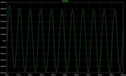
First, the circuit, with U2 input connected to ground - this is a no feedback situation.
Just to give some perspective to beginners, here is a simulation, using as a load a real speaker model (also posted in the forum):
U1 is a high gain voltage stage (gain = 10K, BW = 30MHz) like the input section of an amp, U2 is an unity voltage/high current gain stage, like a triple EF output.
Zo is the open loop output impedance of U2.
The components to the right of Zo model the speaker, to which a 10V peak (possibly a very high value) back EMF is apllied at 110 Hz, where the speaker is reactive.
First, the circuit, with U2 input connected to ground - this is a no feedback situation.
Attachments
Part 3
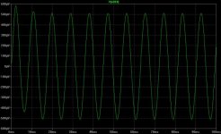
Now, let's close the NFB loop, connecting the + input of U2 to the output of U1.
The voltage at the right side of Zo is some 500uV peak, showing that damping has increased about 1000 times.
The question then is; how was this achieved, which are the effects on sound quality?
Now, let's close the NFB loop, connecting the + input of U2 to the output of U1.
The voltage at the right side of Zo is some 500uV peak, showing that damping has increased about 1000 times.
The question then is; how was this achieved, which are the effects on sound quality?
Attachments
Part 4
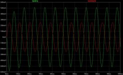
Here we have the voltage ar the output of U2 - 500 mV, the same value there was at the amp's output before feedback!
Just ot make it clearer, it's shown also the EMF voltage in red just to make it clear that U2's voltage is almost 180 deg out of phase with the EMF one.
As a conclusion, no additional stress was placed in the amp (in both cases the amp's output was 500 mV) due to feedback.
Attachments
to my ears continually referring to “back emf” in describing loudspeaker/amplifier interaction is extremely dissonant, like using “scattering coefficient” for resistance or “recombination rate” for transistor current gain – it is a physically correct, useful concept at a detailed level in the modeling hierarchy but using it where the higher level model works is a kind of intellectual “thought impediment” akin to stuttering in speech – it derails more discussions of dynamic loudspeaker behavior than it informs
the useful electrical terminal model of a dynamic loudspeaker is that of a complex impedance composed of the voice coil electrical parameters coupled to a electro-mechanical transformer that converts the force and velocity at the voice coil to electrical terminal I and V – the mechanical mass, spring constant and damping of the cone/suspension/box look like additional C, L, and R at the dynamic driver’s electrical terminals
the linear model of the loudspeaker load as a complex impedance network gives pretty useful estimates of I, V and phase with whatever signal you care to convolve with it
dynamic loudspeaker drivers are noticeably nonlinear, particularly at low frequencies, these nonlinearities can be accommodated in the electrical terminal model of the driver, see:
http://www.klippel.de/background/introduction.asp
you can find hard numerical data in Klippel’s work that permits putting strong limits on how much loudspeaker nonliearities can influence dynamic driver electrical terminal behavior
as ingrast has pointed out laundry lists of possible physical effects are not useful to the engineer until you can put numbers on them to rank their relative influence, Klippel’s models let you bound the possible effects of driver nonlineariy
one physical effect that can readily be dismissed by consideration of the numbers is “microphone” effect:
dynamic loudspeakers are “bi-directional” transducers so that the law of reciprocity applies; a loudspeaker is as efficient in converting incident sound pressure on its cone to electrical terminal I,V as it is in converting the electrical input to sound – since direct radiator dynamic drivers struggle to reach even 1% efficiency any “round trip” electrical – sound – electrical effects are < 0.01% of the power into the speaker’s electrical terminals, since we are dealing with driver resonace peaks, voice coil heating dRseries and crossover impedance dips of > +100%/-50% the microphone behavior of the loudspeaker is merely a curiosity
jcx
I tried to make an expalanation that non-engineers, but with general knowledge of electronics could understand.
The 'Back EMF' name was focused in that audience.
I tried to make an expalanation that non-engineers, but with general knowledge of electronics could understand.
The 'Back EMF' name was focused in that audience.
not blaming you Jorge, Graham’s recent writing has stuck us with the term for now, I am surprised John Curl hasn't been by to claim priority over Graham with his "Interface Intermodulation Distortion" from the '70s
Of course Bode formalized sensitivity analysis of linear feedback networks in his book in 1945 which allows calculating the effect of feedback on the output impedance of an amplifier
In “modern” (maturing in the 60s) control theory you will see "disturbance" input blocks that model noise, distortion or "exogenous"(external) inputs to the control system, the output disturbance sensitivity/rejection with respect to a disturbance signal source connected to the output is a 1st order design goal in control theory however much Graham’s writing makes it seem a new subject
Reducing nonlinear effects is the first, and major motivating advantage claimed for the invention of negative feedback in Black's patent - the objection that linear theory doesn’t apply because we're interested in nonlinear effects is naive; from the outset of negative feedback engineers have been exploring theoretical extensions such as "local linearization" and the small gain theorem to explain and expand on the distortion reducing effect of negative feedback observed in real world circuits
Cherry specifically addressed the "interface intermodulation distortion" issue in audio power amplifiers in the 80's in several JAES articles
To have to deal with Graham"s imprecise, even misleading “discussion” in the face of such a rich background of engineering history is frustrating, maybe you can lead some current diyers confused by Graham’s writings into the beginnings of this well understood subject (by "engineers" in the large, if not enough audio designers)
jcx
I feel the biggest problem to real audio advancement is that 'miths' are treated as 'truth', in a religious way.
I have no dubt that a given amp driven by a given source and driving a given set of speakers may sound better to someone's ears.
Then this system becomes the rule by which all others shall be judged, as an absolute reference.
One should be humble enought to recognise that such a reference doesn't exists, even live music is not a reference - one likes simphonic orchestra, other likes hard rock...
And it's interesting that this thread has been read over 150 times and no other posts besides ours...
Re: Part 4
Jorge,
May I be # 151... 😉
So far, no surprises. The damping with fb increased 1000 times because you have 60dB of feedback. The input at U2 is still 500mV (actually a little less, about 0.1% less, that's where the remaining 500uV come from), but in opposite phase because it has to cancel the impressed voltage. Agreed so far?
Jan Didden
Jorge said:Here we have the voltage ar the output of U2 - 500 mV, the same value there was at the amp's output before feedback!
Just ot make it clearer, it's shown also the EMF voltage in red just to make it clear that U2's voltage is almost 180 deg out of phase with the EMF one.
As a conclusion, no additional stress was placed in the amp (in both cases the amp's output was 500 mV) due to feedback.
Jorge,
May I be # 151... 😉
So far, no surprises. The damping with fb increased 1000 times because you have 60dB of feedback. The input at U2 is still 500mV (actually a little less, about 0.1% less, that's where the remaining 500uV come from), but in opposite phase because it has to cancel the impressed voltage. Agreed so far?
Jan Didden
Jorge,
Maybe we should try to get a bit closer to real life. What about rolling off the gain of the input amp with a simple RC at the output, say starting at 1kHz, to emulate a real amp? See if there appears an 'internal overdrive' as some will claim? Then do the same with a 10kHz signal impressed?
Jan Didden
Re: Part 4
???

In the open loop configuration you had 500mV at the right side of
Z0, but the output of U2 was probably zero.
In closed loop the right side of Z0 is regulated close to zero, but
the output of U2 is now showing 500mV in counterphase. There is
additional stress to the amp. How about analyzing the current through Z0 in both cases? I guess it will be about around 6% higher in the closed loop configuration.
Anyway, the additional load usually is not much trouble for an amp.
But you already have posted the most important question:
How does this differnce sound?
Well, I guess for this question this simple model is not suited, because it has no frequency dependency of the feedback and also
no nonlinearyties. And even if you would place these effects to the
simulation, even then the model would just deliver some graphs and numbers. But no audiable human perception...
Nevertheless- I like your simulation, because it shows the idealised
behaviour of an nice working feedback.

Jorge said:Here we have the voltage ar the output of U2 - 500 mV, the same value there was at the amp's output before feedback!
Just ot make it clearer, it's shown also the EMF voltage in red just to make it clear that U2's voltage is almost 180 deg out of phase with the EMF one.
As a conclusion, no additional stress was placed in the amp (in both cases the amp's output was 500 mV) due to feedback.
???
In the open loop configuration you had 500mV at the right side of
Z0, but the output of U2 was probably zero.
In closed loop the right side of Z0 is regulated close to zero, but
the output of U2 is now showing 500mV in counterphase. There is
additional stress to the amp. How about analyzing the current through Z0 in both cases? I guess it will be about around 6% higher in the closed loop configuration.
Anyway, the additional load usually is not much trouble for an amp.
But you already have posted the most important question:
How does this differnce sound?
Well, I guess for this question this simple model is not suited, because it has no frequency dependency of the feedback and also
no nonlinearyties. And even if you would place these effects to the
simulation, even then the model would just deliver some graphs and numbers. But no audiable human perception...
Nevertheless- I like your simulation, because it shows the idealised
behaviour of an nice working feedback.
janneman said:Jorge,
Maybe we should try to get a bit closer to real life. What about rolling off the gain of the input amp with a simple RC at the output, say starting at 1kHz, to emulate a real amp? See if there appears an 'internal overdrive' as some will claim? Then do the same with a 10kHz signal impressed?
Jan Didden
Good point.
For this you should set a limiter (clipping at 3V) behind U1, set gain of U1 to about 100 then a 1K/160nF low pass in front of U2 and give U2 a gain of 20, and last but not least the Z0 could be 1...2 Ohms.
This set up is closer to a real system. Probably the back EMF will not cause any clipping.
But try to look what's happening at the output of U1, if you give rectangular input signals to U1.....
Have fun
Markus
jcx said:
Impressed. Didn't imagine the situation was that bad ...
Rodolfo
ChocoHolic said:[snip]But try to look what's happening at the output of U1, if you give rectangular input signals to U1.....
Have fun
Markus
Nice intellectual exercise, but not applicable to audio I think, Markus!
Jan Didden
Re: jcx
It does happen. But then we must recognize there are some kernels of truth behind some claims (I am not talking about the "snake oil" ones like directional-grain-cryostaticaly-optimized-high-end-audiophile-quality stuff).
There are no questions at the professional engineering level about NFB (industrial, comunications, medical etc.) as long as the homework is properly done.
Sadly it is also true lousy design practices in the consumer field lead to mediocre products easily spotted by well meaning users and reviewers.
Perhaps too much blind faith in that NFB is a cure-for-everything has made for badly designed amplifiers, where the inherent flaws can at most be attenuated but not sufficiently.
Rodolfo
Jorge said:I feel the biggest problem to real audio advancement is that 'miths' are treated as 'truth', in a religious way.
...
It does happen. But then we must recognize there are some kernels of truth behind some claims (I am not talking about the "snake oil" ones like directional-grain-cryostaticaly-optimized-high-end-audiophile-quality stuff).
There are no questions at the professional engineering level about NFB (industrial, comunications, medical etc.) as long as the homework is properly done.
Sadly it is also true lousy design practices in the consumer field lead to mediocre products easily spotted by well meaning users and reviewers.
Perhaps too much blind faith in that NFB is a cure-for-everything has made for badly designed amplifiers, where the inherent flaws can at most be attenuated but not sufficiently.
Rodolfo
janneman said:
Nice intellectual exercise, but not applicable to audio I think, Markus!
Jan Didden
Hi Jan,
yes rectangular signals are not typical in audio.
But you can have such overdrives already with signals that
simply contain a good portion of HF-noise.
Many amps have a simple low pass at the input to avoid
such TIM distorsions.
But honestly speaking, up to know I did not face major
trouble with that effect.
My main trouble typically were cross over distorsion, thermal compensation....
And most difficult (!): Proper frequency compensation
at any crazy load....
Re: Re: Part 4
100%, Jan
U1, as posted, has a GBW of 30Mhz, and a gain of 10K. So roll off starts at 3Khz (although not explicitly shown).
But I can run the sim with other values.
janneman said:Agreed so far?
100%, Jan
janneman said:What about rolling off the gain of the input amp with a simple RC at the output, say starting at 1kHz, to emulate a real amp?
U1, as posted, has a GBW of 30Mhz, and a gain of 10K. So roll off starts at 3Khz (although not explicitly shown).
But I can run the sim with other values.
Re: Re: Part 4
Right. U2's output is just a few uV.
I do not agree. Making U2's output impedance close to zero and then lumping the real output impedance in Zo is simply a convenient way to show what's going on.
If the output current and voltage are the same, stress is the same, no matter where one shows it.
You're right. Open loop the peak current in Zo is .975A and in closed loop it's 1.023, or about 5% more, very close to your estimate.
It does. GBW for U1 is 30MHz, so gain starts to fall above 3 KHz.
Thanks, that was the idea.
ChocoHolic said:???
In the open loop configuration you had 500mV at the right side of
Z0, but the output of U2 was probably zero.
Right. U2's output is just a few uV.
In closed loop the right side of Z0 is regulated close to zero, but
the output of U2 is now showing 500mV in counterphase. There is
additional stress to the amp.
I do not agree. Making U2's output impedance close to zero and then lumping the real output impedance in Zo is simply a convenient way to show what's going on.
If the output current and voltage are the same, stress is the same, no matter where one shows it.
How about analyzing the current through Z0 in both cases? I guess it will be about around 6% higher in the closed loop configuration.
You're right. Open loop the peak current in Zo is .975A and in closed loop it's 1.023, or about 5% more, very close to your estimate.
Well, I guess for this question this simple model is not suited, because it has no frequency dependency of the feedback
It does. GBW for U1 is 30MHz, so gain starts to fall above 3 KHz.
Nevertheless- I like your simulation, because it shows the idealised
behaviour of an nice working feedback.
Thanks, that was the idea.
ChocoHolic said:
set gain of U1 to about 100 ........and give U2 a gain of 20, and last but not least the Z0 could be 1...2 Ohms.
I'm not following you here. Most SS amps have a voltage gain stage from input to the VAS and a current gain (with a slight voltage loss) output.
And I believe the .5 ohms Zo is representative of a well designed triple EF stage.
But it would be simple to increase Zo and re-run the sim.
Re: Re: jcx
That's so true!
Originally posted by ingrast
Perhaps too much blind faith in that NFB is a cure-for-everything has made for badly designed amplifiers, where the inherent flaws can at most be attenuated but not sufficiently.
That's so true!
- Status
- Not open for further replies.
- Home
- Amplifiers
- Solid State
- Back EMF - some considerations