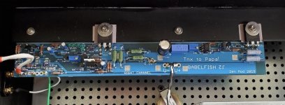
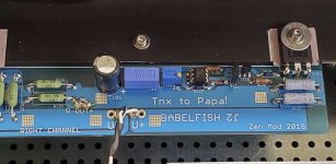
Late to the party as usual, but the boards are finally soldered up and waiting.
I'd like to put to use a 500VA 2x22V transformer, any issues other than maybe having to lower the bias depending on heatsinks ?
Thanks
I'd like to put to use a 500VA 2x22V transformer, any issues other than maybe having to lower the bias depending on heatsinks ?
Thanks
Late to the party as usual, but the boards are finally soldered up and waiting.
Thanks
Fantastic! 😀
Fantastic! 😀
Yeah... I wonder if "procrastination" is recognized as a mental disease in my country....
It has been a while since I got the boards (Thanks ZM). Iron Pre is singing joyfully, this is next.
Looking at boards, am I understanding the NTC board correctly? If used for 2 transformers (with a single primary each), It seems to be setup for 1 NTC per transformer.
My transformers have 2 parallel 110V primaries each. I have 2 of these (antek AS-1218), to use one per channel. I am familiar with 2 NTC per transformer (1 per primary). By (functionally) renaming terminals I can use this for 1 transformer.
Is there a more elegant solution ?
Thanks
Last edited:
that's obviously my omission - making them for my neck of wood, for 2 Donuts, and not counting on fact that in your neck of wood it's good for just one
send me an e-mail , reminding me what's in question, and I'll send you another small NTC pcb, so you'll have it neat
send me an e-mail , reminding me what's in question, and I'll send you another small NTC pcb, so you'll have it neat
that's obviously my omission - making them for my neck of wood, for 2 Donuts, and not counting on fact that in your neck of wood it's good for just one
send me an e-mail , reminding me what's in question, and I'll send you another small NTC pcb, so you'll have it neat
Thank you, and also for the quick reply.
Mighty ZM. When matching 2sk2145 devices do you only match fet to fet or does each side of each fet need to be matched?
as you see from schematic, I'm using each 2SK2145BL as single JFet
so , testing one tiny bugger as simple device, two of them inside being connected in parallel
so, 4 of them in LTP, nice quartet , practically being octet
as seen in second picture in post #3
so , testing one tiny bugger as simple device, two of them inside being connected in parallel
so, 4 of them in LTP, nice quartet , practically being octet
as seen in second picture in post #3
Thanks ZM. I won’t pull what’s left of my hair out trying to match both sides on top of every package. 😱
oh yeaah
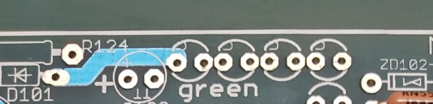
'twas my attempt to be smarter than Eagle, which is not having C mark for Cathode
so, there it is ..... it took me just few years to finally understand how to edit existing and make new packages
Whoa, Blue Car! .......... I even made my own for 2SK77B and for Mos-pucks
'twas my attempt to be smarter than Eagle, which is not having C mark for Cathode
so, there it is ..... it took me just few years to finally understand how to edit existing and make new packages
Whoa, Blue Car! .......... I even made my own for 2SK77B and for Mos-pucks
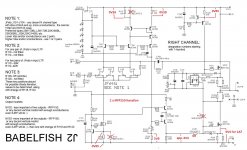
chart of voltages for Babelfish J2
I am trying to fire up my amp, but am not able to get current through the power fets.
Rails are about 24 VDC plus and minus, separate dual mono supplies.
I am using IRFP150 in both the M102 and M103 positions.
All parts are as called out by ZM.
The led's all light fine, the offset can be adjusted no problem.
When I adjust P102, however, nothing happens, with only about 20 mV across either R133 or R136, and minimal current across any of the power resistors.
It is acting the same in both the right and left channel when they were tested separately.
Does anyone have schematics with expected voltages, so I can do some trouble shooting in the optoisolator CCS, bias and emiter follower areas, especially.
thanks
Attachments
it's late now in my neck of wood and I'm sleepy
will be back to you tomorrow
in a meantime , check notes in schematic , what appropriate values of few resistor positions are for all IRFP iteration
will be back to you tomorrow
in a meantime , check notes in schematic , what appropriate values of few resistor positions are for all IRFP iteration
thanks, ZM
I have the jumpers where they are supposed to be, the correct value R110 and R114 for the 4 jefts, and confirmed the 1R0, 0r47, and 0R68 power resistors are in the right places for IRFP150 power mosfets.
I have the jumpers where they are supposed to be, the correct value R110 and R114 for the 4 jefts, and confirmed the 1R0, 0r47, and 0R68 power resistors are in the right places for IRFP150 power mosfets.
- Home
- Amplifiers
- Pass Labs
- Babelfish ᄅſ....or FW J2 on Steroids .... or Not your Father's J2!