Ok thank you, I have finally got it together but didn't have the courage to turn it on today! I'm a bit ill and the brains not working so well 🙂
Give it a go tomorrot
Give it a go tomorrot
Good afternoon gentlemen,
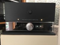
I just finish to build my Korg Triode preamplifier and it is sounding really great !
See attached picture.
I would like to warmly thank Nelson and Jim ( 6L6) and all of you for your support and help.
I am just feeling a little “sad” to have finished so quickly and need, now, a new DIY project... let’s continue to discover and enjoy audio DIY.
Yours sincerely
TYM
Attachments
Good afternoon gentlemen,
I just finish to build my Korg Triode preamplifier and it is sounding really great !
See attached picture.
I would like to warmly thank Nelson and Jim ( 6L6) and all of you for your support and help.
I am just feeling a little “sad” to have finished so quickly and need, now, a new DIY project... let’s continue to discover and enjoy audio DIY.
Yours sincerely
TYM
That is very nicely executed! I like the clear front and the ability to see the Korg glowing inside.
I'm also using mine with an ACA. I am amazed at the performance of that combination. Spent a couple of hours in front of it last night in fact. As soon as the Italians return from their month long vacation/shutdown and send me the 4U chassis I have on order, I have an F5 populated and ready to go into it. I'm really looking forward to seeing what that will do to the sound. That was my next DIY project. This is very addicting!
Again, great looking build!
Hello Papa,
Ahhh, that phase and H2 polarity bit is decidely not easy: just when I thought I got it right I am confused again by your last post. Perhaps you could enlighten me?
My understanding of your last post is that that inverting the polarity at source level (such as some dac allow it) before the B1 KORG would not have the same result as switching the LS cables as proposed usualy. I must say I am lost.
I do understand that some LS have their drivers in opposite phase, due to their filters phase rotation mainly and then some inner driver connecting tries to get it kind of right. That's a given for a LS once it leaves factory, a fix relationship.
Now, if we proceed as in the paper, say we have original polarity at the source, B1 KORG inverts it and then you need indeed to switch LS cable to get your initial polarity back in. The LS then deliver whatever they are supposed to deliver as per factory re drivers and frequency band.
Now if I have a given signal, but decide to invert it at DAC / source level, the B1 KORG gets inverted polarity at its input... and gives initial polarity back at its output. So I would think LS can be connected as usual and all ends up being the same as in the inital proposal, that is the LS then deliver whatever they are supposed to deliver as per factory re drivers and frequency band... Err, or not?
In my case, I plan to have the DAC polarity inverted, then running the B1 KORG in the 13V region to benefit from negative H2 phase (so H2 in opposite phase to signal, whatever polarity that is) at its output but then I plan to leave of course the LS connected as usual, so not inverting them as the signal shuld then be polarity correct while having H2 in negative phase.
Am I wrong?
Sorry, headache!!! Thanks for your kind help
Claude
Listen to your system with speaker cables connected normally, and with the speaker cables inverted. Keep them which ever way you decide you enjoy more. Easy! 🙂 🙂 🙂
In my case, I plan to have the DAC polarity inverted, then running the B1 KORG in the 13V region to benefit from negative H2 phase (so H2 in opposite phase to signal, whatever polarity that is) at its output but then I plan to leave of course the LS connected as usual, so not inverting them as the signal shuld then be polarity correct while having H2 in negative phase.
You have it right, except you misspelled "should"
Thanks Papa and Jim, all clear, sorry for my confused mind and LOL indeed on "shuld" - prefer indeed by far to have only that bit wrong before going to bed 🙂
Enjoy your day very much and again thanks
Claude
Enjoy your day very much and again thanks
Claude
Last edited:

Thank You Nelson
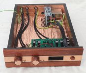
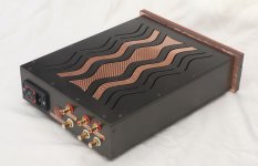
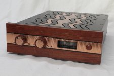
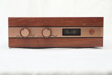
Finally go the job done. I really like the sound, and I'm expecting my son will as well.
Finally go the job done. I really like the sound, and I'm expecting my son will as well.
Attachments
DQ828,
Absolutely stunning chassis work!! Beautiful build, I’m sure your son will enjoy this preamp.
Absolutely stunning chassis work!! Beautiful build, I’m sure your son will enjoy this preamp.
That is over the top impressive. Major skills and imagination there. Makes me want to up my game on my wood working.
What Chassis is that you started with? Did it have the vents on top or do you use a router to make those?
What Chassis is that you started with? Did it have the vents on top or do you use a router to make those?
Last edited:
Finally go the job done. I really like the sound, and I'm expecting my son will as well.
Well done and creative. Excellent build!
Wow that's an impressive build!
What is the bronze/copper coloured material and how did you cut it? Looks great.
What is the bronze/copper coloured material and how did you cut it? Looks great.
That is over the top impressive. Major skills and imagination there. Makes me want to up my game on my wood working.
What Chassis is that you started with? Did it have the vents on top or do you use a router to make those?
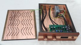
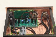
The Chassis is made from plywood laminated with fiberglass, obviously the P&F is nonconductive so I have added a thin layer of copper (0.1mm) sheet to the inside surfaces. When I put the internal copper sheet on it looked terrible, so I spent a stupid amount of time applying a pattern to it (patina pehaps) by hand, and then over coated with clear sealer. The exterior has a texture coat sprayed on it which is over sprayed with automotive colour.
A couple of years ago I built myself a CNC router, so it was used for all of the routing, engraving, and the Engine Turning pattern on the exterior copper (0.55mm thick). The CNC router open up a whole world of possibilities.
Once I sort out some other project (they take forever) I will build one for myself.
Last edited:
I forgot to say, thankyou to all for the feedback & I assume the last post answers all of the questions
The Chassis is made from plywood laminated with fiberglass, obviously the P&F is nonconductive so I have added a thin layer of copper (0.1mm) sheet to the inside surfaces. When I put the internal copper sheet on it looked terrible, so I spent a stupid amount of time applying a pattern to it (patina pehaps) by hand, and then over coated with clear sealer. The exterior has a texture coat sprayed on it which is over sprayed with automotive colour.
A couple of years ago I built myself a CNC router, so it was used for all of the routing, engraving, and the Engine Turning pattern on the exterior copper (0.55mm thick). The CNC router open up a whole world of possibilities.
Once I sort out some other project (they take forever) I will build one for myself.
You have incredible skills. I can tell there are many hours tied up in this build. Kudos to you sir.
- Home
- Amplifiers
- Pass Labs
- B1 with Korg Triode