And how do you explain that (in my case) the aleph sounds better with B1 than without? tryed different sources it is always the same aktive pre sounds better than passive to me. Also tryed a 10k R2R ladder passive pre same result.
So buffer is only needed when source is capable driving cable pot + amp is not the only answer to this Problem.
maybe active pre will sound better for folkdeath too? and it will be an improvement for him?
So buffer is only needed when source is capable driving cable pot + amp is not the only answer to this Problem.
maybe active pre will sound better for folkdeath too? and it will be an improvement for him?
In my experience simple buffers nearly always perform better than passive preamps/potentiometers. Don't know why but the experiments with passive (even though they're appealing) ended long ago for that reason. Only when amp boards were a one board solution so input selection, volume control and power amp on one single board things went smooth straight away. It saves some interlinks too.
Thanks everybody for your answers. I have a good idea of advantages and drawbacks. As 6L6 says, if the amp is working good, with no noises or hum, why risking to add something and maybe, noises... Better is sometimes the ennemy of good.
On the other side, a buffer can help impedance matching. I don't know the impedances of my sources. My CD player (Thule CD100) should have a "normal" impedance for such a gear, but I have no clues about my Boozhound RIAA preamp.
I'll think about all that has been said and make my choice.
Technically speaking, the B1 user manual says it draws fewer than 0.02A. Do you think it can cause troubles to power it with the positive rail of the AlephJ?
Each Channel of the B1 uses 6 to 12mA
But you need to get the right voltage to the B1.
That can use up some more current.
An RCRC could adjust the voltage and use almost no extra current, just some capacitor leakage.
A shunt regulator (similar to a DCB1) could use up a 1000mA of extra current.
20mAdc would be no problem for a ClassA supply.
I keep having to remind many here that a Buffer is only needed where a Source is not capable of driving the cable+parallel Receiver impedances.
This demands that the Buffer is at the Source, NOT at the Receiver.
In general, but not exclusively, a low output impedance Source is more capable of driving the next interconnect, than a higher output impedance.
This message is very interessant and helpfull.
As I said earlier, I had no ideas of the output impedance of my sources as it was not given in their specifications. So, I decided to make some measurements. As I have no lab equipement, I used a DMM, some resistors, a test CD and LP with 1kHz sine tracks and this calculator.
The CD player have a 300ohms impedance (which seems to be standard), but the RIAA preamp have 3000ohms.😱
So, with my setup I have a 3000ohms output seeing a 10Kohms potentiometer seeing a 242kOhms amp input. I think there's a mismatch between phono preamp and potentiometer.
If I add a B1, the phono will still see the 10Kohms potentiometer, if I understand correctly the article that describe the B1. So the mismatch will still be here.
Maybe it will be more simple and more efficient to replace my potentiometer by a 25K and keep my amp as it is today.
What do you think?
When I used Pearl2 Phono into B-1, I had plenty of drive....what phono pre are you using? I always find, to me at least, gain preamps better than active buffer preamps like B-1, and both better than just a volume pot....plus you end the compromise of the same impedance in as out.
I find the BA-3 pre with gain better soundwise than my B-1 where F-5 and mid 80's efficiency speakers are used. On some of my higher efficiency horn loaded speakers, B-1 is very nice with F-5. Still prefer gain, however.
For my money, I would build BA-3 as preamp.
Russellc
My phono preamp is a Boozhound (a simple Jfet design based on the Pacific preamp).
I don't wish to add gain as I'm afraid to have problems with volume setting as I had with all my previous amps. Unity gain is OK for me.
The thing I don't understand is how a B1 can solve my impedance mismatch as the phono pre will still see a 10kOhms pot.
I had a strange idea during the night (night ideas are often strange😉). What I'm trying to do is to lower the output impedance of my phono pre so it could drive the 10k potentiometer.
So why not put a buffer before the pot?
It could be a B1 with no potentiometer nor selector, placed in my phono pre chassis and powered by the regulated 24V PSU the pre uses. I presume the B1 pot must be replaced by a loading resistor (50 or 100k should be ok, no?).
Could it work like this or is it just a stupid idea?
I had done it. We called it double decker b1 where 2 PCBs stacked on each other. First buffer W and CW were shorted and respective toggle switch position hard wired.
I used it with LSA volume control which has 13K ohm impedance. It helped to improve SQ of my tuner. Other sources, it was insignificant improvement.
Sent from my E6 using Tapatalk
I used it with LSA volume control which has 13K ohm impedance. It helped to improve SQ of my tuner. Other sources, it was insignificant improvement.
Sent from my E6 using Tapatalk
I had done it. We called it double decker b1 where 2 PCBs stacked on each other. First buffer W and CW were shorted and respective toggle switch position hard wired.
I used it with LSA volume control which has 13K ohm impedance. It helped to improve SQ of my tuner. Other sources, it was insignificant improvement.
Sent from my E6 using Tapatalk
What are "W" and "CW"?
Here is link for my build,
http://www.diyaudio.com/forums/showthread.php?p=4082056
Sent from my iPad using Tapatalk
http://www.diyaudio.com/forums/showthread.php?p=4082056
Sent from my iPad using Tapatalk
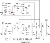
No. Those 1M resistance R201 and R101 are doing that job.Thanks. Something like this, I presume (see attached file).
If shorting CW and C, don't we need to put a load resistor between CW and CCW to replace the impedance of the pot?
Sent from my E6 using Tapatalk
a Buffer is only needed where a Source is not capable of driving the cable+parallel Receiver impedances.
Put the Buffer inside the Turntable along side the phono pre with it's ultra short phono to pre cablesI had a strange idea during the night (night ideas are often strange😉). What I'm trying to do is to lower the output impedance of my phono pre so it could drive the 10k potentiometer.
So why not put a buffer before the pot?
You increase the signal as early as possible and make the output capable of driving the next cable.
All you need is a very basic CCS loaded jFET Follower. Just 2 transistors per channel.It could be a B1 with no potentiometer nor selector, placed in my phono pre chassis and powered by the regulated 24V PSU the pre uses. I presume the B1 pot must be replaced by a loading resistor (50 or 100k should be ok, no?).
Could it work like this or is it just a stupid idea?
You can go more complicated, eg Calvin, or Salas, or Juma, but these are just the same jFET followers.
The Salas RIAA is a RIAA amplifier with a jFET Follower tacked on the end to drive the next cable. Have a look Just 2Q added @ the right hand end.
Last edited:
Thanks Andrew.Put the Buffer inside the Turntable along side the phono pre with it's ultra short phono to pre cables.
Inside the turntable, it won't be possible as my plinth is not "hollow". But I'm plannig to put the buffer inside the phono pre, so cables will be very short (no more than 10cm).
Like a B1?😉 Or is there other examples. Being a newbie in DIY, I prefer to work with a PCB rather than point to point wiring.All you need is a very basic CCS loaded jFET Follower. Just 2 transistors per channel.

Last edited:
No. Those 1M resistance R201 and R101 are doing that job.
Sent from my E6 using Tapatalk
In the article on Passdiy, it's said that the input impedance is the one of the pot although the 1Mohms resistors are here. So I wonder what happens if you remove the load of the pot...
- Home
- Amplifiers
- Pass Labs
- B1 preamp build thread