Now it fits 5th's criteria!! The frequency response is near perfect!
Can I make a guess though? This will NOT sound nearly as good as with the original response.
If I am wrong, I will re-think everything I believe about B&W and do the modification to mine too!! 😱😱😱
Can I make a guess though? This will NOT sound nearly as good as with the original response.
If I am wrong, I will re-think everything I believe about B&W and do the modification to mine too!! 😱😱😱
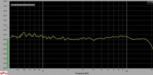
It's even flatter on the listening axis
Fwiw, if there's any difference between before and after it's difficult to detect, but I'm leaning in favour of the original unmodified response.
Holy cow!!! that is a flat response!
Could you please spend a little description as to what you hear from modified and unmodified filter? What is the difference between the two?
Does one of them seem more accurate than the other, or that one of them seem to bother your hear with its peak response while the other doesn't?
BTW you had a GREAT idea,and this test is really interesting and highly valid IMO!
My bet is that the flat frequency response doesn't do much for the sound and very likely there is a good reason for having the original frequency response and I wouldn't be surprised if you like the original better.
If you end up preferring the modified, like I said, I will modify mine too 😱
EDIT: This should answer 5th's observation that I just want to hear that my speaker is great! Not true, if I know for a fact from a valid test that my speaker can be improved, the suggestion is more than welcome! I don't personally care much about B&W and I choose it because of its uncanny sound, but once more, if it can be improved I am on for it, but it has to be done with criteria and proven on the actual listening field and not only left on words and graph's implementations.
Last edited:
fwiw, I constructed a RLC network to reduce the slight peak at 3.5kHz, and a 1 ohm series resistance also reduces the slight rise below 1kHz. I haven't listened as yet but will do so this evening.
It definitely looks flatter.
It's even flatter on the listening axis
Fwiw, if there's any difference between before and after it's difficult to detect, but I'm leaning in favour of the original unmodified response.
Info from the first quote above makes me comment you did two mods at same time, try the RLC alone and toggle that for listening tests. Could be interesting to see a impedance plot before after RLC mod.
I've fine tuned it a little more, so here's the latest plot.
The difference is very subtle but there's just a tad less vocal presence than before. Note that there's a very gentle saddle in the presence region anyway so the slight peak probably compensates for that.
I could easily live with it either way but I'll listen some more before giving my final verdict.
Note that the network is in series with the M-T input on the rear of the speaker. I haven't gone inside the plinth at this stage.
Attachments

Info from the first quote above makes me comment you did two mods at same time, try the RLC alone and toggle that for listening tests. Could be interesting to see a impedance plot before after RLC mod.
true what you say, but if difference is barely audible with two mods, I am assuming with only one i.e. taming the 3K peak, will be even less audible! Just my two cents!
I've fine tuned it a little more, so here's the latest plot.
The difference is very subtle but there's just a tad less vocal presence than before. Note that there's a very gentle saddle in the presence region anyway so the slight peak probably compensates for that.
I could easily live with it either way but I'll listen some more before giving my final verdict.
Note that the network is in series with the M-T input on the rear of the speaker. I haven't gone inside the plinth at this stage.
very interesting. Does the speaker loose in resolution and transparency by adding the extra filter or you feel it has the same quality but more neutral behavior?
If you think that this is a significant improvement or an audible improvement, I will design a board with new parts that will fit on the existing plinth.
One question though: is your peak, given you have the diamond tweeter, different from mine?
Info from the first quote above makes me comment you did two mods at same time, try the RLC alone and toggle that for listening tests. Could be interesting to see a impedance plot before after RLC mod.
Yes, will do as you suggest.
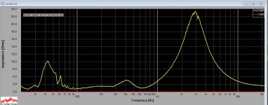
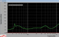
I did an impedance plot several months ago but I'll redo one tomorrow sometime. (earlier plot is attached)
edit. I also constructed an impedance correction network to reduce the ugly phase angle in the bass
Attachments
Last edited:
very interesting. Does the speaker loose in resolution and transparency by adding the extra filter or you feel it has the same quality but more neutral behavior?
If you think that this is a significant improvement or an audible improvement, I will design a board with new parts that will fit on the existing plinth.
One question though: is your peak, given you have the diamond tweeter, different from mine?
The peak comes from the FST mid so it should be the same or very similar in yours.
Fwiw, I'm not using 'audiophile' parts at this stage, although they're not crap either. I'm not hearing any loss in transparency though, but the RLC notch is very high q which probably helps in that regard, because it adds negligible series impedance beyond +/- 500 Hz of the centre frequency.
Art Vandelay,
Thanks the impedance plot from before the mod was done, unfortunately think the RLC network sits in wrong place because now it is working for both FST and tweeter as a EQ in a preamp would do, it is important it sits after the XO components only for FST midrange. Another helper could be do a frequency response measurement with FST or tweeter phase reversed then if the RLC network is tweaked with right component values the phase canceling slopes will show to be more perfect symmetrical in the canceling slope compared to the nonsymmetrical canceling slope the FST resonance ought to look like.
Don't think the components need to be audiophile grade others it benefits ageing and keeping values precision better under varying temperatures.
Don't know which tools you have can i recommend free XSim from bwaslo link is here http://www.diyaudio.com/forums/multi-way/259865-xsim-free-crossover-designer.html. In that program you can setup a amp and a perfect wideband driver, then measure impedance and frequency response for FST only when it sits in actual box and link the zma and frd files to the before mentioned perfect wideband driver. Now you on the fly can tweak impedance and frequency response in real time adding and changing components and their values.
The peak comes from the FST mid so it should be the same or very similar in yours.
Fwiw, I'm not using 'audiophile' parts at this stage, although they're not crap either. I'm not hearing any loss in transparency though, but the RLC notch is very high q which probably helps in that regard, because it adds negligible series impedance beyond +/- 500 Hz of the centre frequency.
Interesting, obviously if the concept works, using proper audiophile parts will improve slightly (Bryrt and others won't agree).
I mean, I am not a speaker designer, but technically wise, the modification you made, improved your response big time but it seemed to be way to easy to achieve that it seems very odd to me B&W didn't think of that.
Only logical thing is you listened to it and see what you like about the solution. Maybe I can listen on my setup too and if the concept works, I will make a PCB design that fits on the original plinth so it will be a drop in replacement. However so far I am a little skeptical listening test will tell if this is the right path or not.
Art Vandelay,
Thanks the impedance plot from before the mod was done, unfortunately think the RLC network sits in wrong place because now it is working for both FST and tweeter as a EQ in a preamp would do, it is important it sits after the XO components only for FST midrange..
This is a very good point actually.
B&W clearly possess the technical ability to design a crossover that would perform far better but they do not.
Brand identity is an important thing with loudspeakers, some companies design specifically for a house sound and some design for absolute accuracy. B&W fall into the former category and also want to use the simplest crossovers that they can. Going for the simplest crossover has an added benefit because it pleases those who like the ideal of simplicity. A simple crossover is also innately cheaper to build, allowing B&W to use a small number of expensive boutique crossover components, which is always a crowd pleaser.
As Byrtt says though you need the notch filter to be positioned so that it's only affecting the midrange and not the tweeter.
Art's description of what the notch did to the sound is fairly normal though, peaks around the 1-3kHz area add forwardness to the sound. Does getting rid of the peak cause a loudspeaker to lose detail, or does leaving the peak in cause a loudspeaker to project unnaturally throughout that frequency band?
Given the opportunity I would really like to redesign the xover for the 800 series. The white paper reads well and measures well within the context of the paper itself, but the real world measurements of the 800 series just don't match up with what B&W show within the paper.
Ideally, yes, the notch should be installed in series with the FST voice coil, as BYRTT has said, - and thanks for the link, I'll install it this evening.
The way forward will be to remove the FST crossover pcb and to run some temporary speaker cables directly to the FST and tweeter, which allows measurements to be made on each driver independently, and will enable me to optimise the crossovers before reinstalling them.
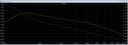
Looking at the FST crossover response (in LTS) it appears to be designed to correct the driver's on-axis response (from Zaph's measurements), but I'm inclined to want to tweak the values so that it's flat at 15 degrees off-axis, which then flattens the power response over a 60 degree window.
I've attached response of the FST with B&W's crossover values, crossing over to a tweeter with a 2nd order L-R filter, and I've also attached the revised crossover with a series notch installed. The best looking Q seems to be achieved with a parallel RLC network; L=0.05mH, C=39uF, R=12. (and assuming that the inductor has a parasitic resistance of 0.1 ohms)
The way forward will be to remove the FST crossover pcb and to run some temporary speaker cables directly to the FST and tweeter, which allows measurements to be made on each driver independently, and will enable me to optimise the crossovers before reinstalling them.
Looking at the FST crossover response (in LTS) it appears to be designed to correct the driver's on-axis response (from Zaph's measurements), but I'm inclined to want to tweak the values so that it's flat at 15 degrees off-axis, which then flattens the power response over a 60 degree window.
I've attached response of the FST with B&W's crossover values, crossing over to a tweeter with a 2nd order L-R filter, and I've also attached the revised crossover with a series notch installed. The best looking Q seems to be achieved with a parallel RLC network; L=0.05mH, C=39uF, R=12. (and assuming that the inductor has a parasitic resistance of 0.1 ohms)
Attachments
Last edited:
I did a little bit of simulating with this and from my quick playing around with LspCAD the parallel connected notch filter, in series with the driver doesn't appear to be work anywhere near as well as as a series connected filter placed across the drivers terminals. The series connected one has the added advantage that nothing is going to be placed in the signal path, but it does have one caveat, the inductor size required is immense. Now the series resistance of the notch string is very high, so this does mean you could use very thin wire for a high DCR then reduce the size of the resistor.
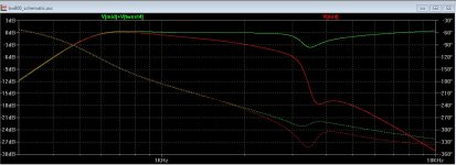
In this case the notch in question is comprised of R1061, C1061 and L1061.
In this case the notch in question is comprised of R1061, C1061 and L1061.
Attachments
I vote for a series RLC in parallel with the driver.
You can probably do exactly the same job with either
type of a network, only a parallel one with the driver
seems cheaper. 29 awg Jantzen coil has dcr of 11ohm
and costs a few bucks. Beats the price of a 39uF poly
cap.
You can probably do exactly the same job with either
type of a network, only a parallel one with the driver
seems cheaper. 29 awg Jantzen coil has dcr of 11ohm
and costs a few bucks. Beats the price of a 39uF poly
cap.
Last edited:
is it basically a start redesigning crossover for 800 deal now? 😕
I was under the impression that Art stated that making the response perfectly smooth was barely audible and after all the original was preferable anyway.
I will follow with great attention especially considering that Art will be comparing new solutions vs original in proper set up and unbiased mind.
Just want to throw in my two cents as good design practice for audio: technical "perfection" should not be achieved by adding extra complexity, but rather with elegant simple solution. In other words, if you want a flat response, you should redesign the drivers and keep crossover to its minimum required to achieve your goals if no-compromise approach was the ideal goal.
Adding series and parallel RLC to the crossover to compensate for drivers, IMO is not the way to go.
Anyway, like I said, I will be following with interest and if in the end the new crossover works better, thus provides sonic advantages and I am not talking about only measurements, but speaker will posses after extensive listening sessions more utter transparency, improved texture, speed etc...then I will admit I was wrong about B&W all along.
Just two more cents on audiophile grade parts: it seems people here are split about this subject and I am sure that now all audiophile boutique parts are worth of any considerations, however this is not true in general and in a blind test on my personal developments with electronics, a V-CAP CuTFT for instance is miles ahead of a standard Wima capacitors to make one name.
A reference speakers such as 800 or any other speakers in the same price range or more, uses reference audiophile grade parts and it's not purely to attract potential foolish customers, which most of them, won't even look what's inside the crossover, but to achieve best sound.
Simple reasoning linr: beside few people, DIY world here is made out of cheap skates who want to make things on their own and will never spend $$ to buy commercial expensive stuff. Conversely, the audience who buys 800, Magicos and other expensive speakers or audio gear, will not care the slightest what parts are used inside and has no knowledge as to what a mundorf cap is. So if a company wants to make max profit there would be no need to throw 5 $100 cap when they can reach same sonic result with $2 one and people actually don't care either way.
Anyway...spent too many words on this....but I felt the need to throw in my personal experience and opinion on this.
Just want to throw in my two cents as good design practice for audio: technical "perfection" should not be achieved by adding extra complexity, but rather with elegant simple solution.
A good design practise for engineering in general is to come up with the simplest elegant solution that gets the job done properly.
In other words, if you want a flat response,
You should always want a flat response.
You should redesign the drivers and keep crossover to its minimum required to achieve your goals if no-compromise approach was the ideal goal.
A simple crossover is worthless if it does not do the job properly and will sound far worse than a more complex version that meets proper specifications. No compromise means not being afraid of doing what's necessary to end up with excellent end results. KEF are well known for using highly complex crossovers in their reference series and they review excellently, the trick is knowing the best way to go about engineering towards excellency without sacrificing anything.
The B&W FST driver is actually a very well engineered driver, the only fly in the ointment is that resonance at 3.3kHz and you can bet B&W went through many cone iterations until they found the one that worked the best!
Adding series and parallel RLC to the crossover to compensate for drivers, IMO is not the way to go.
Adding a series connected RLC in parallel with the drivers terminals is a fairly standard thing to do and is in no way detrimental. You add in no series pass elements so there are no added insertion losses, in effect it's a completely transparent crossover.
You will get no argument from me though with passive crossovers I really dislike adding in extra series pass elements unless they are absolutely necessary. Shunt components are a different matter entirely though.
on first point we both agree on the same thing, well engineering is minimum elegant design that gets job properly done. Excellent or state of art engineer is same criteria but get job perfectly done.
Accordingly to either criteria, what is attempted or suggested here is basically trying to put a patch to an apparent flow on a state of art design. Remember that 800 is the pinnacle i.e. state of art of a company with a great reputation on the audio market.
Second point: the fact you should want a flat response is something I fully agree with you, but trade offs can be had if this produces a recognized superior sound. what we still don't agree on is that flat sound is NOT a guarantee of good sound!!! Also, When I say trade offs I am referring to a reasonable deviation from flat response. Obviously in this case, the deviation is really minor and proven fact is that a modified crossover with flat response is barely audible accordingly to Art first impressions.
When B&W designed this speaker, I am sure they spent countless hours of listening, tweaking and measurements and it seems now that a couple of simulations and analysis which are obvious to the least skilled engineer and surely didn't skip the eyes of the engineer team at b&W, should now transform a terrible speaker into an amazing one.
Then again, accordingly to your line of reasons, all the speakers that have a flatter frequency response than the 800 should sound better. I am sure I Can find a best buy speaker that has a flatter freq response, now you want to tell me this will sound better than an 800 on a high level system?
Again, we keep going back to the same point, you have not listened to the 800 and before assuming it is terrible because it has that little deviation, you should take a listen to it. I am sincerely startled by the fact you would probably listen to a 500 dollars speaker that has a flat response, rather than a 800 reference speaker which is acknowledged worldwide.
This debate is actually fun I would really like to understand your logic behind your line or reasoning.
On the third point, I fully agree with you, series elements should be avoided as much as possible.
Anyway like I said, time will tell as it seems that Art is willing to go through a crossover redesign. Should this make my speaker sound even better I will definitely have learned something new and have to give you my best cudos.
Nevertheless so far you can only have my skepticism.
Simple reasoning linr: beside few people, DIY world here
is made out of cheap skates who want to make things on
their own and will never spend $$ to buy commercial
expensive stuff.
You call your reasoning simple, I call it lack of know how.
This is simple reasoning. If you make your money the easy way,
then you have no respect for it and you will spend it in the same
way you got it. If not, then you will be careful about it.
- Home
- Loudspeakers
- Multi-Way
- B&W Signature 800 upgrade diamond tweeter