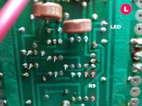
You're going to have to look at the traces on the back of the board to determine where R9 is located.
And the color bands on the resistor will likely be orange-orange-red-red.
Correct, thanks!!
Ok, so R9 is good.
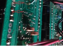
Here is updated pics ... notice the bubbly protectant layer ...
Attachments

Last edited:
For grins, I have the amp powered up to check DC offset ... another 10 minutes.
Interesting thing ... while L channel (good) is dropping values, and I expect to get under 5mV ... the R channel (bad) is standing at -80.7V
Not sure if this means anything, but wanted to post. Once the amp warms up and I can double check good channel DC offset, I'll report back.
I am powered up on variac/dbt ... just in case.
DC Offset reading after 10 minutes.
L = ±1mV (LED on steady)
R = -75.1V
-----
Got to run out for a couple hours, but can get back to this upon my return. I realize it's New Years Eve, so I don't expect anyone to respond later in the day. I really appreciate your help guys!
L = ±1mV (LED on steady)
R = -75.1V
-----
Got to run out for a couple hours, but can get back to this upon my return. I realize it's New Years Eve, so I don't expect anyone to respond later in the day. I really appreciate your help guys!
Last edited:
That's quite common. It just means the board was solder coated before the resist was applied.Here is updated pics ... notice the bubbly protectant layer ...
DC Offset reading after 10 minutes.
R = -75.1V
Oh, oh. I'll turn you back over to Chamberman.
Hmmm. Ominous. Well, enjoy a safe New Year's gentlemen if I am not able to check back today. No rush, other than I just want to get to a point where I can decide if I'll push forward with ordering parts. I like Chamberman's advice to determine the issue first.
Just looking around for the big cans, if I have to replace ... and can't find any new ones. Unless I am willing to believe ebay sellers.
Cans in there now are:
15,600uF -10 + 75%
75 VDC 95 surge
85 C Max Ambient
3186GE153U075AMA1
362 9143 56699
Screw top (distance ~33mm)
Dimensions: ~4.125"h x ~3"w
Cans in there now are:
15,600uF -10 + 75%
75 VDC 95 surge
85 C Max Ambient
3186GE153U075AMA1
362 9143 56699
Screw top (distance ~33mm)
Dimensions: ~4.125"h x ~3"w
Yeah -75V on the speaker output is not a good situation. Hopefully one of the outputs isn't shorted because your repair gets expensive then.
Measure the following 3 points in reference to the bottom of R9 where the black arrow is pointing. #1 & #3 should measure the same unless the trace is opened up somewhere.
There should be plenty of replacement capacitors available to replace the large cans. You need to look at 80VDC caps as they are more common than the 75VDC. If you need the same 3" diameter then you may even need to move up to a 100VDC. If you're seeing close to 80VDC on the rails then you need to probably move up to an 85vdc or higher rated capacitor. Typically they jump from 80 to 100vdc in their ratings.
Attachments
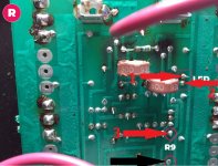
#1 & #3 measure ~33k on both boards. Consistency = good
#2 give me values all over on BOTH boards ... depends on getting a good spot on the pins ... at first, the values jumped up, then finally settled down to the values below. The bad R channel seems to be dropping a tenth every second ...
R = 8.xM ohms and decreasing value, as I hold probes
L = 4.31M ohms
If I have to get MOSFETs, I do trust the seller I talked to, who is not on ebay. It's the batch he bought from Japan back in 2009. They are older than that. Pairs are not matched as far as I know, and are 26 euro / pair. He has three pair left.
Last edited:
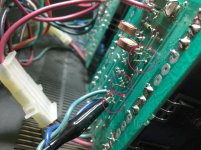
No I'm looking for the voltage measurements at those points with the amp powered on. Careful you don't slip a probe you don't need any added damage.
No I'm looking for the voltage measurements at those points with the amp powered on. Careful you don't slip a probe you don't need any added damage.
Yikes, ok, I'll do that tomorrow ... some pins are close, so I'll have to be super careful. I am measure VAC or VDC? I may try to see if I can get a micro clip on the R9 leg we are measuring across.
Try to stand it up on the heatsinks. Then you can probe downward instead of trying to go in from the top. This is what I do normally because its easier to control the meter probes like this.
Boy ... I'm really not willing to take a mighty chance of arcing the board when I'm probing. I think what I would need to do is solder a short length of wire (from surplus capacitor) so I can use a clip, without it coming off.
I tried on the bad board with #3 and got 0.000vac reading ... but as I mentioned before, I have to move the probes around the pin to get a solid connection, ie, reading.
I'll give this a go later. I have to run out for a bit for family stuff. I'll report my findings later today.
I tried on the bad board with #3 and got 0.000vac reading ... but as I mentioned before, I have to move the probes around the pin to get a solid connection, ie, reading.
I'll give this a go later. I have to run out for a bit for family stuff. I'll report my findings later today.
- Status
- Not open for further replies.
- Home
- Amplifiers
- Solid State
- B&K ST-202 Plus :: hum