These caps take a while to discharge ... in the past, I could leave a whole day, and when trying to pull fuses on the underside of the power supply board, I would get spark/shorting.
I looked under the PS board with a little "dental" mirror and the fuses look fine. I could see, with light, any issues on traces, but it's hard to see.
Do you want my next step to be the ohm reading in post #180?
Since it could take till tomorrow before the power caps discharge ... maybe I should first to post #179.
What do you think?
I just realized why you are concerned the voltage is higher than the rating on the power supply caps ... hmm ... is this the job of the rectifier?
No the transformer sets the step down voltage. On multi-voltage international versions the input windings can be changed to retap the transformer to operate on a higher or lower voltage. I had an amplifier one time that had 105vdc on the main DC rails. Someone had changed the voltage tap settings and added nearly 20vdc to the DC rails.
Gotta run down for dinner ... be up in a bit. Thanks for your help. Feel free to tell me we'll look at tomorrow, or whenever you have time this week.
From one Texan to another (I presume), thanks! 🙂
From one Texan to another (I presume), thanks! 🙂
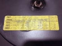
What, am I reading the transformer sticker correctly?
It looks like the secondary windings (x2) have output of 43v ????
Yes, but this should be the RMS AC voltage with the transformer fully loaded. Unloaded the AC voltage will go up a good bit. Not only that but after being rectified and capacitively filtered, you'll end up with a DC voltage about 1.35X the VAC RMS output rating.
These caps take a while to discharge ... in the past, I could leave a whole day, and when trying to pull fuses on the underside of the power supply board, I would get spark/shorting.
I looked under the PS board with a little "dental" mirror and the fuses look fine. I could see, with light, any issues on traces, but it's hard to see.
Do you want my next step to be the ohm reading in post #180?
Since it could take till tomorrow before the power caps discharge ... maybe I should first to post #179.
What do you think?
It shouldn't take that long for these caps to discharge especially if the working channel is connected and properly biased. Its hard to believe that B&K didn't install bleed resistors in the power supply board but looking at your picture of the PS board I see they didn't install any. They must've expected the output stage to discharge the main caps. Which is bad because if you blow the fuses the caps never discharge and can hold a high charge level. If its taking that long for the main caps to discharge then you need to install some bleed off resistors across the main filter capacitors. Get a pair of 2 or 3W resistors of 4 - 6k ohm and install one across the screws of each cap. Then the rails will bleed off in a minute or two after being powered off.
Last edited:
From one Texan to another (I presume), thanks! 🙂
Happy to help!
It shouldn't take that long for these caps to discharge especially if the working channel is connected and properly biased. Its hard to believe that B&K didn't install bleed resistors in the power supply board but looking at your picture of the PS board I see they didn't install any. They must've expected the output stage to discharge the main caps. Which is bad because if you blow the fuses the caps never discharge and can hold a high charge level. If its taking that long for the main caps to discharge then you need to install some bleed off resistors across the main filter capacitors. Get a pair of 2 or 3W resistors of 4 - 6k ohm and install one across the screws of each cap. Then the rails will bleed off in a minute or two after being powered off.
It would appear they were going for a simple circuit?
I may have to order two of those resistors ... I'm assuming that I just loosen the screws and put a bend in the leads so that when I tighten, they will hold firm?
I found two 4.7k ohm 2W green resistors left over from another project. That'll work, eh?
Yes, but this should be the RMS AC voltage with the transformer fully loaded. Unloaded the AC voltage will go up a good bit. Not only that but after being rectified and capacitively filtered, you'll end up with a DC voltage about 1.35X the VAC RMS output rating.
The local "tech" said the amp put out 150 wpc ... this amp is rated for 200 wpc. I wonder what connection his reading (if valid) relates to the issue we are trying to track down.
It would appear they were going for a simple circuit?
I may have to order two of those resistors ... I'm assuming that I just loosen the screws and put a bend in the leads so that when I tighten, they will hold firm?
I found two 4.7k ohm 2W green resistors left over from another project. That'll work, eh?
Yes, 2W 4.7k will work. Just install them as you suggested with kinked leads under the capacitor screws.
You can temporarily use one of them to bleed off the caps by holding the resistor body safely with insulated pliers and using the resistor to short across the capacitor screws for 30SEC or so. Then measure the DC volts on the cap to see if you need to bleed it off some more. Be careful there'll possibly be high voltage there for the first several seconds that you start doing this.
Many times I'll use a grabber lead to bleed off the main capacitors. Clip the resistor to one end of the grabber lead then clip the opposite end to one of the cap screws and use the insulated grabber end with the resistor to short to the other capacitor screw.
Then move the grabber lead to the other capacitor and do the same thing there. Once again be careful to only be touching insulated leads or clips.
Then move the grabber lead to the other capacitor and do the same thing there. Once again be careful to only be touching insulated leads or clips.
The local "tech" said the amp put out 150 wpc ... this amp is rated for 200 wpc. I wonder what connection his reading (if valid) relates to the issue we are trying to track down.
I have to discount those measurements in relation to what we're looking for, they came from the working channel.
Gotcha ... I'll pick this up in the morning and short the caps if necessary so I can get measurements.
Go ahead and ohm out those 4 fuses under the power supply board once you have the capacitors discharged to install the bleed resistors. Then if all 4 fuses check good perform the check in post #180.
Go ahead and ohm out those 4 fuses under the power supply board once you have the capacitors discharged to install the bleed resistors. Then if all 4 fuses check good perform the check in post #180.
I leave the fuses in place while I ohm out ?
Okay, all four PS board fuses measure under 1 ohm ... three are about 0.3 ohm, and one is 0.6 ohm.
- Status
- Not open for further replies.
- Home
- Amplifiers
- Solid State
- B&K ST-202 Plus :: hum