Okay so 66mV on the R-ch is elevated but is in no way high. Is it adjustable?
Have you connected a speaker to the R-ch and checked to see if its passing a signal?
Not yet.
On the subject of the fuses you listed. The 6A fuses in the power supply rails sound correct for a 200W amp. The 8A 32V fuse in the AC mains location is incorrect and should be an 8A - 125V or 250V rated fuse.
The closest I have is 10A 250V ... I can go by store today.
The speaker protection fuses both those in the rear fuse holders near the binding posts and those mounted on the channel boards can be whatever you want them to be. Instead of one of us typing out a lengthy reason you should read this Hafler XL-280 manual page 5 about the speaker protection fuses.
I'll have a read, thanks!
What is the setting on the variac when you get this "no hum, or very little"? i.e what is the AC input voltage to the amp at that time? Measure the AC input voltage with your meter, being extra careful around that line voltage.
I ran the variac all the way up to 120, and there was never a hum at any point. The measurements I gave were at 120V.
Adjust the variac so that the AC line input voltage is the same as if you plug it directly into an outlet. Is the hum different between direct line and the variac set for direct line voltage?
I'll have to check that a little later.
Thanks!
Not yet.
The closest I have is 10A 250V ... I can go by store today. Does it matter if the fuse for the AC power line is MDL? I'm guessing not. I can't believe I didn't find a shop today that has any 8A fuses of any wattage. I will try again tomorrow.
I'll have a read, thanks!
I ran the variac all the way up to 120, and there was never a hum at any point. The measurements I gave were at 120V.
!
I believe your hum problem is a DC component coming in on the mains that when coupled with the older loose windings on your transformer creates the audible hum. As someone pointed out many posts back. This is somewhat proven out with the filter (variac) you're putting inline that blocks the DC component and stops the hum. Although annoying its not a showstopper.
If one of your channels is not biasing or passing music that would be a showstopper.
Earlier in the process, there was no hum with the variac. There is now, after the visit to the tech. Turning the bias down on the good channel, lowered the hum to normal on the transformer, so I'm wondering if worse-case scenario, I'm looking for a good output board ...?
I'm happy with stepping away from this until the end of the week. I won't have enough time to properly do anything. Thanks guys!
Merry Christmas to you all 🙂
I'm happy with stepping away from this until the end of the week. I won't have enough time to properly do anything. Thanks guys!
Merry Christmas to you all 🙂
Kenwood61
I'm confused.
In post #117 you said there was "no hum or very little" when connected to the variac.
In post #122 you said the "I ran the variac all the way up to 120, and there was never a hum at any point."
I believe both of these were after the tech visit unless I missed something.
I'm confused.
In post #117 you said there was "no hum or very little" when connected to the variac.
In post #122 you said the "I ran the variac all the way up to 120, and there was never a hum at any point."
I believe both of these were after the tech visit unless I missed something.
You are right. There was a point, I believe, before going to the tech where I started getting hum even on the variac.
So on my last test, I did find that when I turned the bias pot down a little, the hum went away. So either the bias was set too high, or there is something going on there. If I have time today, I may hookup a check speaker to the good channel and see what I get.
So on my last test, I did find that when I turned the bias pot down a little, the hum went away. So either the bias was set too high, or there is something going on there. If I have time today, I may hookup a check speaker to the good channel and see what I get.
Had some time to hook up amp to cheap test speakers. Nasty loud hum through the speakers. First time for that. I'm hoping it's a bad cap/component on board.
I will most likely have to ship this to a tech I trust. But since there are few components on the board, I'd like to do the component update/replacements since I enjoy that, and I know I can't mess anything up. After pulling output boards, I can use my transistor tester on the Mosfets.
Questions.
1) Will my PEAK Atlas DCA55 be able to measure the Mosfets on the bad channel, to at least determine if any are bad?
2) If so, can I leave them fastened to the heat sinks, and desolder from board? Or do I need to remove from the heatsinks? If I remove, I'm guessing it's best to get new thermal pads?
3) Is there anything needed on the filter board at the power caps? I'm thinking of removing to double check solder traces for cracking and reflow.
4) Anything else I should consider doing?
My goal is to do the leg work on component updates, and I can select the parts I want to use ... but since I don't have scopes, etc, I have to rely on someone else. I should say that on my Sansui BA-3000 that was not working when I bought it ... with help from board members, I was able to do all the work on replacing all electrolytics, including the zobel network, and all faulty parts - resistors, transistors, etc. I got it working in great order, with lots of help, only to have a low level ground hum that I eventually sent the amp out. The fix was removing two protection relays, and molex connectors that were causing the problem. Amp works great.
So based on this experience with a much more complicated amp, I'd like to do most of the work, if it's not a foolish thing to do. After all, this is a DIY forum. 🙂
Here are a few tips.
The lateral mosfets used in these amps are relatively robust. If you don't measure full rail voltage on the speaker terminal, they are likely fine. However, you can measure if they are shorted with your multimeter set on ohms. With no rail voltage remaining on the large filter caps, discharge the gates of the outputs and then measure if they are shorted. Likely when they were checked for you, they showed shorted, or low ohms because the gate was still charged. It's possible your tech couldn't read the datasheet for these outputs (if they even looked) and assumed they were BJT outputs. Also take note that the leg arrangement on these are not the same order as other mosfets, these are G S D.
If in fact you do have bad output mosfets, Exicon makes replacements that are new and not counterfeit. ECX10N20 and ECX10P20 are their part numbers in the T0-247 case. If you need them, you should get them matched because it looks like your amp does not use source resistors.
Its possible your main filter caps are due for replacement along with the few electrolytic caps on the amplifier boards. Beware, the traces on the circuit boards for B&K amps are fragile. They can lift very easy with too much heat and tear out with component removal due to burs left on the component leads from the flush cutters that were used. Plus, it also looks like repairs may have already been performed on your amplifier boards, so they could already be pre-weakened for you.
Earlier (Post #82), you stated the transformer still had hum after removing the rail fuses. You can take this one more step further by removing those fuses again, and unscrewing the filter caps. Is the hum still there? All that remains on the secondary side would be the bridge rectifier at that point. IF the hum is still there after disconnecting the filter caps, you could further test by removing the rectifier from the equation, fully confirming it is a faulty transformer.
Another tip is purchase and build the soft start and speaker protection kits found in the diyAudio Store. I just installed this kit (both boards) in one of my B&K amps. The fuses are not really going to protect valuable speakers.
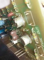
One last thing, I am pretty darn sure those LEDs are not supposed to be lit when the amplifier is operating correctly at idle.
The lateral mosfets used in these amps are relatively robust. If you don't measure full rail voltage on the speaker terminal, they are likely fine. However, you can measure if they are shorted with your multimeter set on ohms. With no rail voltage remaining on the large filter caps, discharge the gates of the outputs and then measure if they are shorted. Likely when they were checked for you, they showed shorted, or low ohms because the gate was still charged. It's possible your tech couldn't read the datasheet for these outputs (if they even looked) and assumed they were BJT outputs. Also take note that the leg arrangement on these are not the same order as other mosfets, these are G S D.
If in fact you do have bad output mosfets, Exicon makes replacements that are new and not counterfeit. ECX10N20 and ECX10P20 are their part numbers in the T0-247 case. If you need them, you should get them matched because it looks like your amp does not use source resistors.
Its possible your main filter caps are due for replacement along with the few electrolytic caps on the amplifier boards. Beware, the traces on the circuit boards for B&K amps are fragile. They can lift very easy with too much heat and tear out with component removal due to burs left on the component leads from the flush cutters that were used. Plus, it also looks like repairs may have already been performed on your amplifier boards, so they could already be pre-weakened for you.
Earlier (Post #82), you stated the transformer still had hum after removing the rail fuses. You can take this one more step further by removing those fuses again, and unscrewing the filter caps. Is the hum still there? All that remains on the secondary side would be the bridge rectifier at that point. IF the hum is still there after disconnecting the filter caps, you could further test by removing the rectifier from the equation, fully confirming it is a faulty transformer.
Another tip is purchase and build the soft start and speaker protection kits found in the diyAudio Store. I just installed this kit (both boards) in one of my B&K amps. The fuses are not really going to protect valuable speakers.
One last thing, I am pretty darn sure those LEDs are not supposed to be lit when the amplifier is operating correctly at idle.
RiLoWa
The K405 & J115 devices are not lateral mosfets, see this thread for more detailed info. There are no equivalents that are produced any longer.
B&K used the laterals you referenced in their later amps however I'm not certain what changes were made to the circuit to allow for their implementation. Its possible that the new laterals could be used in this older B&K amp, but he would have to dig to find out what, if any, changes might need to be made.
Also, the LED which is shown in post #19 of this thread should absolutely be on all the time. It is the voltage reference for the LTP tail. If its going out then there is a serious problem somewhere. There are only a few reasons that LED should go out when the power switch is ON and that would be,
1- Loss of +DC RAIL voltage. Which could be due to a blown + rail fuse (if its blinking then its not blown), cracked intermittent traces, solder joints or bad wiring).
2- Open resistor or failing LED
3- Loss of ground or poor ground continuity on the affected channel.
Although the LED or R9 could be going bad its doubtful.
I'm leaning towards cracked traces or problems in the wire harness. The fact that it seems to blink when a heavier load is placed on the amp tells me that either the DC volts are dropping too low under load due to a high resistance in the DC supply voltage circuit or the ground is insufficient to support the higher power output. This means that as the load rises the ground is likewise rising up to some level well above zero volts due to a high resistance (open wire, bad pin in a connector, cracked trace, etc) in the ground path.
Thanks for the info guys. It looks like I'll need to pull the boards apart to check traces, replace caps, and possibly, remove suspect parts to test.
If I am 90% sure, or better, that I'll keep this amp ... as in worth fixing ... I may go ahead and get new power filter caps. If this amp is going to be used for years to come, it might as well have new caps.
It wouldn't hurt to examine all wiring. There isn't that much, so it shouldn't be a problem.
The DIY Audio Store kit looks like a fun build.
Soft Start & Speaker Turn-On Delay / DC Protector Combo – diyAudio Store
I'll need to count the cost within ballpark before I push forward.
Kenwood61,
I wouldn't buy or do anything to the amp at this point. I would first focus on why this LED is not illuminated, it should always be on. If you find the problem with the LED you may inadvertently find the source of all of your other problems.
With the amp powered off measure the resistance of R9 is it approximately 33k?
Power the amp on and measure the voltage drop across the LED, it should be probably 1.7V - 2V.
Then measure the voltage drop across R9 it should be just a few volts lower than the main +DC rail.
If either of those voltage measurements is not right then measure voltage from the top of the LED to the bottom of R9 (ground). You need to do this right at the pins of those components because this will help to pin point if you have a supply or ground problem or if the LED or resistor is bad. You should see full +DC rail voltage here. If this voltage is drastically low then either the supply or ground path is compromised somewhere.
Last edited:
I attached the schematic so we're on the same page.
You may want to try and verify that this schematic matches your board. There appears to have been many different variants of these amps over the years so its possible that this schematic is different.
You may want to try and verify that this schematic matches your board. There appears to have been many different variants of these amps over the years so its possible that this schematic is different.
R9, if it's the right resistor, has following values, after connecting to power supply ... not powered:
R = 67.1 ohms
L = 69.9 ohms
I had to move the probes around on the pins to get a good reading.
R = 67.1 ohms
L = 69.9 ohms
I had to move the probes around on the pins to get a good reading.
Attachments
Last edited:
R9, if it's the right resistor, has following values, after connecting to power supply ... not powered:
R = 67.1 ohms
L = 69.9 ohms
I had to move the probes around on the pins to get a good reading.
Pull the rail fuses and try reversing the probes. You likely are getting a sneak path through one of the transistors.
Not connected to power supply ... pulled fuses on output boards and values are the same. Maybe this resistor is not R9? The resistors are so close to the board, I can't read them, and I'm not confident of my ability to read the schematic, if it is indeed correct.
Last edited:
Not connected to power supply ... pulled fuses on output boards and measure is the same. Maybe this resistor is not R9? The resistors are so close to the board, I can't read them, and I'm not confident of my ability to read the schematic, if it is indeed correct.
Based on the schematic it could be R8/R9/R10, at 67 ohms that must be R10. But its still is measuring wrong in the bad channel.
R9 must be located elsewhere possibly down by the where the ground enters the board.
- Status
- Not open for further replies.
- Home
- Amplifiers
- Solid State
- B&K ST-202 Plus :: hum