That is substantially different than yours. The rectifier and fuses are chassis mounted, while yours are on the circuit board. The output transistors (FETS) are in TO-3 cases instead of your TO-220/TO-202 (or similar) cases. The way the boards are mounted is probably a consequence of the difference style transistors.
So based on your earlier post, the output mosfets are going to cost 26Eur per pair and you need three pairs and they need to be Vgs matched between the 3 N-types and 3 P-types. This guy is going to charge you more for this matching. Matched pairs typically sell for more money than random pairs. With shipping you'll end up having $100 easily in just the replacement output mosfets for one channel and you haven't even looked into the drivers or anything else that needs to be replaced when you change the outputs.
Why not buy something like this amp which the auction just ended on a few days ago and didn't sell for the listed price BTW. Then use one of the output modules from it to get your amplifier going. Literally in one hour you're done, no worrying about whether the outputs are fake, whether they are Vgs matched or if other parts need to be replaced. As a plus you have a spare channel module to keep your prized ST-202+ going for many years.
I know its more expensive, but your buying a whole lot more equipment for your $$$ and in a way insurance that it WILL be fixed when you're done. Especially when you factor in that you have limited equipment available to you to perform this type of repair work, i.e. a scope, 4 & 8 ohm dummy load, proper signal generator, etc.
Chamberman, are you convinced his right side amp is actually bad? I'm not. I'm waiting for him to plug it back in, power the amp, and find out if it blows any fuses.Why not buy something like this amp which the auction just ended on a few days ago and didn't sell for the listed price BTW. Then use one of the output modules from it to get your amplifier going.
Chamberman, are you convinced his right side amp is actually bad? I'm not.
No I'm not convinced either, more investigation is needed.
I'm just covering that aspect and the alternative because he had brought up the replacement parts in Croatia.
Kenwood61, The only difference I can think of between removing the fuses (which you did and it had no effect on the mechanical hum) and unplugging that molex connector is the ground wire. Removing the fuses would not sever the ground.
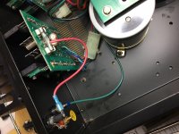
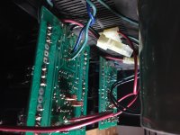
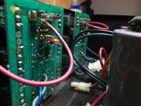
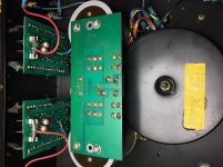
How many wires are attached to each amplifier module? I see: the red/black/green on the molex connector, the red that goes out to the speaker fuse, and the blue/green twisted pair that connects to the input RCA. Are there any others?
Also Kenwood61, I see no 'protection' circuitry on this amp. Leave the speakers disconnected until we can confirm the output offsets are good. Wouldn't want to smoke your speakers.
Last edited:
I'll get to all the questions now that I have a little time.
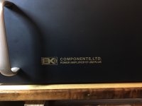
First off, my amp is the gold lettering, older version, unless there were later models that used the early faceplates. I can't find any information to support this.
Here are some pics that we can reference.
First off, my amp is the gold lettering, older version, unless there were later models that used the early faceplates. I can't find any information to support this.
Here are some pics that we can reference.
Attachments
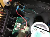
How many wires are attached to each amplifier module? I see: the red/black/green on the molex connector, the red that goes out to the speaker fuse, and the blue/green twisted pair that connects to the input RCA. Are there any others?
Also Kenwood61, I see no 'protection' circuitry on this amp. Leave the speakers disconnected until we can confirm the output offsets are good. Wouldn't want to smoke your speakers.
Correct, there is no protection circuitry. That's why each channel out has a fuse, as well as AC fuse. Fuses galore.
There are ONLY five wires attached to output boards ...
- blue/green twisted pair is from INPUT
- red/green/black wires from the molex connectors
The green wires going to black speaker terminals and input ground are all coming from the chassis star ground, between the power filter caps.
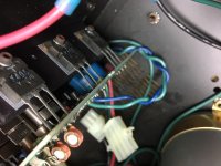
There is a black square plastic housing on the underside of the power filter cap board ... is that a rectifier?
So based on your earlier post, the output mosfets are going to cost 26Eur per pair and you need three pairs and they need to be Vgs matched between the 3 N-types and 3 P-types. This guy is going to charge you more for this matching. Matched pairs typically sell for more money than random pairs. With shipping you'll end up having $100 easily in just the replacement output mosfets for one channel and you haven't even looked into the drivers or anything else that needs to be replaced when you change the outputs.
Why not buy something like this amp which the auction just ended on a few days ago and didn't sell for the listed price BTW. Then use one of the output modules from it to get your amplifier going. Literally in one hour you're done, no worrying about whether the outputs are fake, whether they are Vgs matched or if other parts need to be replaced. As a plus you have a spare channel module to keep your prized ST-202+ going for many years.
I know its more expensive, but your buying a whole lot more equipment for your $$$ and in a way insurance that it WILL be fixed when you're done. Especially when you factor in that you have limited equipment available to you to perform this type of repair work, i.e. a scope, 4 & 8 ohm dummy load, proper signal generator, etc.
To be honest Chamberman, there is something that got me musically about this amp when I had it running. I wasn't looking for another amp. So if it turns out that it's not worth getting this amp running correctly, I'll need to either sell and try to get my $83 back, or part it out. But I'm not there yet. With Christmas and family stuff about to get into full swing, I may need to wait till next weekend to pick this back up. But, I can do quick things during the week, and today, I'm ready to power this puppy up, if you guys think it's not a bone head move. I won't connect anything.
FYI, I did pick up some $20 speakers this past week just for stuff like this. If they blow, no big deal.
Oh, and the "matched" pairs in Croatia. They aren't "matched", I meant that they are the correct matching pair. Sorry for that confusion. If I bought the pairs he has, it would be 26 euro for "a pair", plus about 8euro shipping. So close to $90USD. But I don't want to spend that and find out I didn't need to.
Yes, a bridge rectifier. The rest is as I expected.There is a black square plastic housing on the underside of the power filter cap board ... is that a rectifier?
I couldn't wait ... so I plugged the molex connect on the R channel back ... powered up on the variac/dim bulb tester, went bright, then dimmed ... extremely low hum, barely there, just like I like, but no LED light on the output board showing current. I adjusted bias, as the tech turned it to zero ... I had noticed before in my adjustment process that the lights would go dim/out when bias was turned off. So now that the light is not on, and no fuses blown, that I can see ...?
With power on, measure the DC voltage at the filter caps. One side should be positive, the other negative, and could be quite high (60 volts or more). Now put the voltmeter into the AC mode and see if you can measure any significant AC voltage across those filter caps.
DC = 65V each side, within ~ .2V rang
AC = 0V ... I get some values bouncing around quickly, but settle to 0VAC
First off, my amp is the gold lettering, older version, unless there were later models that used the early faceplates. I can't find any information to support this.
Kenwood61
Your amp is probably a very late model 1st gen just before the Sonata (blue lettering) series came out. Many times when a change in production of a product is coming the parts for the next gen stuff will come online and still use the prior production parts. Some of the parts are mingled between series in the final months before a changeover. This is fairly common, you don't want to just throw away a hundred or so cases or faceplates so you keep running the old ones until they're gone.
The good news in this is that I was worried that there might be some very early 2nd gen Sonata series that had the early model steel TO-3 output modules. Your amp proves that this should not be the case. All of the Sonata stuff with blue lettering should have the later amp output modules with the TO-3p plastic devices (I said earlier they were TO-264 but they are actually TO-3p style) because B&K switched to those devices while the gold lettering faceplates were still in production. However if you're buying a 1st gen with the gold lettering it could go either way. This all assumes that your faceplate is factory original and wasn't swapped by someone, this would not be very likely though.
What is the serial # of the unit you have? Any # after yours should be the TO-3p output version.
We definitely need to figure out if your original is working properly though, there may be nothing wrong with it.
Use your voltmeter to confirm there is not any excess DC at the speaker terminal. Hook up you speakers and play some tunes. Hopefully, both channels will be functional.
Assuming you have audio out of both channels,
Now back to what seems to be a mechanical hum...
With both channels connected note the mechanical hum
Disconnect the right channel, and note the mechanical hum
Plug the right channel back in, and unplug the left channel. Note the mechanical hum.
Can you draw any conclusions from that?
Does this amp have a two prong or three prong power plug? If three prong, try plugging it in using one of those three prong to two prong adapters - leaving the ground wire on the power adapter unconnected. Then if possible, turn the plug around to reverse the 'ac polarity'. Any clues here?
TO-202, TO-220, TO-264, TO-3p, too many package variations. That last makes the least sense from a nomenclature standpoint - a TO-3p is nothing like a TO-3. 🙂
Use your voltmeter to confirm there is not any excess DC at the speaker terminal. Hook up you speakers and play some tunes. Hopefully, both channels will be functional.
DC Right = -66mV ... but heat sink is cold ... something on this board is not working.
DC Left = 2.0mV ... within spec
Assuming you have audio out of both channels,
Now back to what seems to be a mechanical hum...
With both channels connected note the mechanical hum
Disconnect the right channel, and note the mechanical hum
Plug the right channel back in, and unplug the left channel. Note the mechanical hum.
Can you draw any conclusions from that?
Hooked up to variac/dbt, no hum, or very little. This level is more than acceptable to me.
Plugged into outlet, I get a hum. So there is something in the variac/dbt setup that eliminates it.
I tried disconnecting each channel. Hum stays the same.
Disconnect BOTH channels, hum goes down where I want it.
So issue is on output boards.
Just for kicks, on the L channel that has output ... I adjusted bias to see if it would change hum. It did. It reduced so that hum went away ... or to the almost non existent level. Heat sink cooled off and is lightly warm in idle mode. Nothing is connected. But amp sounds happy.
Does this amp have a two prong or three prong power plug? If three prong, try plugging it in using one of those three prong to two prong adapters - leaving the ground wire on the power adapter unconnected. Then if possible, turn the plug around to reverse the 'ac polarity'. Any clues here?
Two prong ... doesn't matter which way it's plugged in.
Fuses
All the fuses under the filter board have a zig zag look to them. I don't want o pull one now an spark things up ... but there is one just like them in the fuse for the L channel speaker terminal.
From what I can find, and what is stamped on this, it's a Cooper Bussmann Buss Fuse BK/AGC-6 Amp 250V.
The other speaker terminal fuse is a 15A fuse. Doesn't say anything else on it. But the fuses on each output board are the same.
Then there is a third type of fuse that is only on AC power on back. That is 8A 32V 313, and looks like two tightly twisted wire filaments.
So there are three types of fuses. I did swap fuses on each channel out, but no difference.
At this point, the L side may be good, and after warming up the hum goes down. But it appears nothing is happening on the R output board.
I may have to get back on this tomorrow.
Guys, I really appreciate your efforts to help out!!
Okay so 66mV on the R-ch is elevated but is in no way high. Is it adjustable?
Have you connected a speaker to the R-ch and checked to see if its passing a signal?
If you're worried about blowing the speaker in the event of a failure then install a 1A fast blow fuse in the speaker fuse holder and keep your volumes within reason when testing.
On the subject of the fuses you listed. The 6A fuses in the power supply rails sound correct for a 200W amp. The 8A 32V fuse in the AC mains location is incorrect and should be an 8A - 125V or 250V rated fuse.
The speaker protection fuses both those in the rear fuse holders near the binding posts and those mounted on the channel boards can be whatever you want them to be. Instead of one of us typing out a lengthy reason you should read this Hafler XL-280 manual page 5 about the speaker protection fuses.
What is the setting on the variac when you get this "no hum, or very little"? i.e what is the AC input voltage to the amp at that time? Measure the AC input voltage with your meter, being extra careful around that line voltage.Hooked up to variac/dbt, no hum, or very little. This level is more than acceptable to me.
Adjust the variac so that the AC line input voltage is the same as if you plug it directly into an outlet. Is the hum different between direct line and the variac set for direct line voltage?
- Status
- Not open for further replies.
- Home
- Amplifiers
- Solid State
- B&K ST-202 Plus :: hum