Yep she works! Try connecting to the amp again across the fuse holder. Make sure your leads are well attached. If you do not get a reading again then power the amp off and reverse the leads. That shouldn't matter but try it anyway.
Nada. Is it possible the fuse needs to stay in, so that current can cross? Then clip onto each end of the fuse holder to measure current?
The other question ... what about turning the bias pots all the way down, just to see if that effects hum? If we assume bias is high, this could at the very least show that is the case ... if the hum reduces. Just spit ballin with my limited knowledge.
No the meter is passing the current. Is the bias pot turned all the way to one extreme? If so try turning it back the other way to see if any reponse. Careful if it suddenly jumps and you go much past 400mA you'll need a new meter fuse.
When the variac voltage gets up to about 72V the hum gets louder than when the amp is running ... alot louder by the time I get to full voltage ... chassis vibrates. I switched to the 10A setting and tried that, but nothing.
I'll check the bias pot now ...
I'll check the bias pot now ...
Weird .... wasn't getting a reading, but turning the pot a little both ways to see if I'd get anything. Just going back and forth between 0.00 - 0.01mA ... no other value. Just zero to 0.01mA.
I did notice the hum reduce with CCW move on pot.
Gotta go downstairs for a bit, but will check back.
I did notice the hum reduce with CCW move on pot.
Gotta go downstairs for a bit, but will check back.
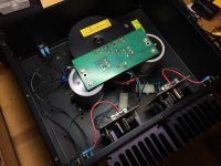
Take a picture of the interior of the amp for me. I looked online and only found one ST202 that looks like your channel board and I cannot see it very clearly.
Are there fuses on the bottom side of the board between the two large power supply capacitors?
Are there fuses on the bottom side of the board between the two large power supply capacitors?
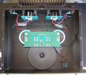

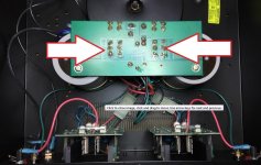
I'm pretty sure the DC rail fuses you need to remove and measure across are under this board.
Blue wire is the negative rail, red wire is the positive rail. You may have to get creative to attach the meter probes under there.
****Nevermind on my comment about the wire color, it looks like B&K didn't follow the normal convention in color coding, I think the black is the neg rail. ****
Blue wire is the negative rail, red wire is the positive rail. You may have to get creative to attach the meter probes under there.
****Nevermind on my comment about the wire color, it looks like B&K didn't follow the normal convention in color coding, I think the black is the neg rail. ****
Attachments
Last edited:
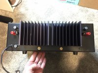
After looking at your pictures the fuse you were removing is a speaker protection fuse. I'm not sure why but there are a second set of speaker protection fuses in the rear panel above the binding posts.
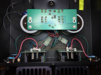
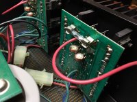
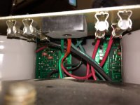
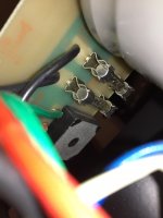
Here's some pics of under the board ... one of the times I'm glad my phone has a camera 🙂
I see two fuses for each channel. Are the outside fuses the pos/neg rails I need to meter?
Red = pos
Black = neg
Gotta run. Sorry. But I'll check back in the morning and after I have my coffee, I'll get to this. I can get probe clips down there.
I see two fuses for each channel. Are the outside fuses the pos/neg rails I need to meter?
Red = pos
Black = neg
Gotta run. Sorry. But I'll check back in the morning and after I have my coffee, I'll get to this. I can get probe clips down there.
Attachments
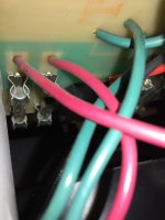

The B&K procedure says to remove the neg rail fuse in each channel for setting the bias. So pull one of the black wire fuses, trace out which channel that black wire goes to and that's the channel you'll adjust once you power it up. Then power down, reinstall that fuse and move to the next fuse.
Make sure you let the amp sit for a couple of minutes between power downs to allow it to bleed off the voltage. I do not see any bleed resistors on the power supply board or across the main caps, they might be on the channel boards, but be careful. You may want to measure the volts across the caps before you pull those fuses to make sure they're bleeding voltage off when powered down.
Also don't forget to turn the bias pots to minimum before you power it up the first time or you risk blowing the meter fuse on the 400 mA range.
Yes there are a lot of fuses in there. You can eliminate one set of the rear speaker fuses. I would personally just use the ones mounted to the channel boards and bypass the fuse holders on the rear panel. I find fuses in the speaker output path to be detrimental to sound quality, you have two of them in series to the speaker, this has to be worse.
Ok. One side done. Strangeness.
Never got above 101mA, as I increased voltage on the variac. Settled at about 99mA ... as I turned the trimpot a little in either direction, readings always stayed within ±3mA ... but after a few turns, the hum level dropped, and the red LED on that channel board started to blink.
After power off, the LED lights on both boards stayed lit ... with the L channel I was working on, still blinking. Previous times of shutting off, both lights went out. So something is different now.
I'll wait awhile and try the other side. If I keep this, I believe at the very least, I would recap output boards and replace trimpots to better multi-turn units. These are 180 degrees.
If the LED you're referring to is the same one shown in the schematic back on page two of this thread then that LED just sets the voltage reference for the LTP tail transistor on the front end of the circuit. It should stay lit continuously. Is it just dimming or actually blinking off/on?
Also those LED's should go off completely when the amp is turned off and the large capacitors bleed off. It should take 10 - 30 secs or so but if its taking a lot longer than it did prior to bias adjustment for those LED's to turn off then you've turned the bias a lot lower than it was. With the output stage bias turned lower (or OFF completely) the main capacitors will stay charged for a much longer time which means the front end LED's will stay on longer.
It sounds like you've got the equipment there to perform the procedure that B&K spelled out, which is feeding a 100mV 20kHz signal to the amp and setting the DC bias in that manner. Maybe you should bite the bullet and try it out.
Those are the LEDs. It is blinking off/on.
I'll try using the tone generator to input with signal ...
I'll try using the tone generator to input with signal ...
No difference ... other than I did adjust trimpot so that LED is on solid. My reading varies around 33-46mA, using Tone Generator on my iPhone6S set at 20KHz ... moving to 10KHz lowered the reading a little.
The tone generator isn't working.
I tried with speakers hooked up, to be the 8ohm load, and just got distortion/hum that was not good. I couldn't turn the variac all the way up without risking the speakers. These are $20 speakers, but sound good, so I know they work (still).
At this point, I'm just going to find someone in town who knows how to do this, and go from there. I may hook up the amp, with my test speakers, to see if it's sounding fine.
- Status
- Not open for further replies.
- Home
- Amplifiers
- Solid State
- B&K ST-202 Plus :: hum