I'm a bit confused here. Originally you said that the transformer was humming, that it was not a hum from the speakers.
This is a mechanical issue. There is something in the transformer that is moving when it should be held still. The best fix would be to either replace the transformer or have it re-varnished by a rewinding shop. Next best is to decouple it from the chassis - the sounding board - so that any vibrations in the transformer are not amplified by other mechanical resonances.
Can it make more noise under load? Yes, but the idle currents are going to be significantly less than the currents in the transformer when it is providing music power to the speakers. Does the mechanical hum increase when you turn up the volume?
Remove the mounting bolt and lift the transformer off its mechanical mount. Is the hum significantly reduced? Try adding some sound dampening material between the transformer and its mounting.
Still think it is excess idle current draw? Just remove those 4 fuses feeding power to the output section (the ones you have been trying to take current measurement from) and turn on the power. Is the hum gone?
Last edited:
Pulled all four fuses and hum is still there. So your point ... not a bias issue ... but transformer. Next, I'll remove bolt and put some damping material I have and see if that removes the hum.
Transformer bolt/nuts are not coming off. I don't want to risk stripping threads on there, and I notice there is a damping pad under the transformer, that is slightly larger. I'm guessing that replacing that with a stronger damping material might work. I have some leftover SoundCoat from a project.
Right now, I need to let filter caps drain so I can put fuses back in and see where I'm at.
One change I may have not pointed out ... prior to today's experimentation, the amp barely hummed at all when plugged into the variac. The hum is louder today.
Right now, I need to let filter caps drain so I can put fuses back in and see where I'm at.
One change I may have not pointed out ... prior to today's experimentation, the amp barely hummed at all when plugged into the variac. The hum is louder today.
OK, so a tech has figured out the problem.
The right channel output card has some shorted MOSFETs. The noisy transformer is caused by half the windings going to ground. Dead quiet when R channel is disconnected. 🙁
Is there a work around, or quality replacement for all the MOSFETs ... since I assume it will be near impossible to find NOS MOSFETs???
I need to figure out if this is something worth pursuing for me, or if it's time to let someone else have a project amp. I know that if there is a fix, the amp will sound amazing. I already have two other amp setups that are better, so I'm not sure there is enough motivation for me to do this and keep ... if it's going to cost too much. What's "too much"? Well, my gut might say $100 ... but knowing myself all too well, it could be up to $250.
You had all the output stage power fuses removed. That would have disconnected any power draw from the right (and left) channel. At that point you still had the hum. How did the tech 'disconnect' the right channel?
He did not remove. He used his transmitter tester.
I'm a long experienced tech, but new to the audio forums. Someone is going to have to explain a 'transmitter tester' to me.
I wish I knew. I'm going to pick it up today. The L channel is fine. But the R channel output board is unplugged until I can decide on the next step.
Seems odd!
If the mosfets in one channel were shorted then a rail fuse, one of the 4 under the power supply board, should have blown. BTW, in a situation like this your killawatt meter will show that an extreme load is being placed on the amplifier. Of course usually a blown DC rail fuse is the indicator of this extreme load.
Unless you can find a forum member here that can supply you with the proper matched K405/J115 triples at a reasonable cost then your ability to repair for the price you listed is near zero. Your only other option is to find another late model (Sonata series blue lettering) ST-202 that will have the proper output modules. You could then swap one of the output modules out and save the other for a future spare. If you can find an ST-202 that is torn up cosmetically this would bring the price down considerably. Just a thought!
Yes. That and the fact that both channels of the amplifier seems to be working, except for the mechanical hum, would preclude the failure of an output transistor.Seems odd!
If the mosfets in one channel were shorted then a rail fuse, one of the 4 under the power supply board, should have blown
I have the amp back home, and here's what I know.
There were some things that concerned me about what the tech said:
in regard to measuring bias, he said
I did find a source online that has 4 matched pairs left of 2SK405-Y/2SJ115-Y for 26EUR each pair. I have one good channel, so only need three pair. I talked to this guy and he says they are genuine. He has them on a site for repair parts for a different brand. He also has a picture of the 50-pack they came in with label showing they were made in 2009. As long as I trust this seller (not on epay), this is a good deal to me and worth it. My investment in this amp is only $83 at this point.
I was thinking of pulling the R channel output board today, so I can use my transistor tester to see which one(s) are bad so I can place an order today.
My concern is that I apparently don't have a local tech that I fully trust to help, as the one who helped me this time said it would cost $500-600 to get running properly, which I don't agree with. Granted, I don't know what is wrong.
If I move forward, I would go ahead and order new caps. But since there are so few components on the output stage boards, it isn't a chore to pull all components on the bad channel, test, and order what I need. Then order a matching component(s) for the good channel to keep things balanced.
I will need some help through this process, and you guys have been very helpful. The other route I can consider is shipping the amp to a tech I trust, from experience.
There were some things that concerned me about what the tech said:
in regard to measuring bias, he said
- “I was able to set bias on left channel using the scope. Which translates to 16mvac at idle no input and 26mvac with the 200mvrms 20khz signal applied measure across fuse holder and fuse removed”
- he also said that when the fuses were out, it didn't effect the amp running. I'm sure he didn't listen to anything through it, but was probably using a scope or analyizer
- he measured power output on the good channel (L) at 153wpc ... this is a 200wpc amp.
I did find a source online that has 4 matched pairs left of 2SK405-Y/2SJ115-Y for 26EUR each pair. I have one good channel, so only need three pair. I talked to this guy and he says they are genuine. He has them on a site for repair parts for a different brand. He also has a picture of the 50-pack they came in with label showing they were made in 2009. As long as I trust this seller (not on epay), this is a good deal to me and worth it. My investment in this amp is only $83 at this point.
I was thinking of pulling the R channel output board today, so I can use my transistor tester to see which one(s) are bad so I can place an order today.
My concern is that I apparently don't have a local tech that I fully trust to help, as the one who helped me this time said it would cost $500-600 to get running properly, which I don't agree with. Granted, I don't know what is wrong.
If I move forward, I would go ahead and order new caps. But since there are so few components on the output stage boards, it isn't a chore to pull all components on the bad channel, test, and order what I need. Then order a matching component(s) for the good channel to keep things balanced.
I will need some help through this process, and you guys have been very helpful. The other route I can consider is shipping the amp to a tech I trust, from experience.
"He has them on a site for repair parts for a different brand. He also has a picture of the 50-pack they came in with label showing they were made in 2009."
Run away from these parts.... These Mosfets haven't been produced since the 90's, so these have to be fakes.
Run away from these parts.... These Mosfets haven't been produced since the 90's, so these have to be fakes.
You said earlier that the tech was going to leave the bad (right) channel unplugged. Can you see what is unplugged and can you post a picture? If you plug that channel back in, does the humming return?
I'm still a bit concerned about our lack of service information for this amp. There is a almost illegible schematic back at post #19, but it seems to be a little inconsistent with the picture of your unit. There are 2 power fuses shown on the schematic (plus a speaker fuse which does not concern us at this time), and we think these are the fuses on the board with the filter caps. But if that is the case, each amp channel would actually need a 4 pin connector to provide 1 - ground, 2 - positive rail, 3 - negative rail, and 4 - input diff pair negative side (unfused). And I only see three wires, maybe your unit uses the fused negative rail for the input pair so doesn't need that 4th wire.
In any case there certainly is some troubleshooting we can do on that amp board before you give up/spend $$$$/throw questionable parts at it.
Excuse the rambling -just the way I think...... When you were trying to adjust the bias, the one channel you could seem to adjust didn't get to spec - it was less. The LED that provides a reference voltage was blinking and not consistant. You said the tech indicated the available output power of the 'good' channel was significantly below spec. Unplugging one channel reduces the load on the transformer/power supply. I wonder if you have a bad bridge rectifier or filter cap.
With power on, measure the DC voltage at the filter caps. One side should be positive, the other negative, and could be quite high (60 volts or more). Now put the voltmeter into the AC mode and see if you can measure any significant AC voltage across those filter caps.
Last edited:
Another thing that doesn't make sense about shorted output devices in one channel is that early on you stated that you were able to adjust the DC offset to zero. Typically the DC offset will be many 10's of volts all the way up to full rail voltage and not adjustable if an output mosfet or transistor is shorted.
If there are shorted devices, they weren't there early on in this process.
If there are shorted devices, they weren't there early on in this process.
"He has them on a site for repair parts for a different brand. He also has a picture of the 50-pack they came in with label showing they were made in 2009."
Run away from these parts.... These Mosfets haven't been produced since the 90's, so these have to be fakes.
I just talked to the seller in Croatia ... he bought the devices from a Japanese seller on that date in 2009. From what I know of this guy, I am inclined to trust him. I may talk to someone who's bought devices from him.
I'll get to the other really good posts from Ylli later ... I have to finish up getting a computer to work right now ... but I see some good actions for me to take and report on!!
Chamberman, you are correct. Originally, that amp sounded GREAT with no issues. This whole adventure began from my problem with mechanical transformer hum. I'm slapping myself, but here we are. I'm in it to the end.
If there was shorting, it's because of testing I did ... or they really aren't shorted.
I don't know how many of you have to use computers, but sometimes I really hate them. I have a moment to post real quick, that back at the computer stuff.
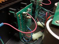
Here is a pick of the connector the tech unplugged ... it's the lines going from filter board to output stage.
In the picture below, it's the white plastic connector. This picture was before going to the tech. I don't have a shot yet of it unplugged, but that's really not necessary at this point.
One other thing ... I'm thinking to be a good steward of this fine piece of audio history, I should replace the power filter caps for longevity. Even if they are "good". Any recommendations? This is one area I don't feel like I have to go for boutique caps ... rather, anything that will be at least equal with original parts.
Attachments
Also, I agree that the schematic provided earlier in the thread is hard to read. I'm going to try to find one. I don't mind buying a pdf download as long as it's correct. Most of what I find are for the later Sonata models, which don't help me.
Check out this video. The Youtube title just says it's a ST-202 ... but you can clearly see the "Plus" on the faceplate. What I want you guys to look at is the additional fuse placed up closer to the power switch, and even bigger change is output boards are turned 90 degrees. I have no idea if there were models in this range that did this from factory, so I'm inclined to contact this guy to ask him. Also, he didn't put the transformer cover back on, and I'm wondering if there is any advantage to this?
YouTube
YouTube
Check out this video. The Youtube title just says it's a ST-202 ... but you can clearly see the "Plus" on the faceplate. What I want you guys to look at is the additional fuse placed up closer to the power switch, and even bigger change is output boards are turned 90 degrees. I have no idea if there were models in this range that did this from factory, so I'm inclined to contact this guy to ask him. Also, he didn't put the transformer cover back on, and I'm wondering if there is any advantage to this?
YouTube
Different amp from yours!
That's an early model (gold lettering) and that amp uses the TO-3 (steel can) style outputs. That's the reason the boards are mounted differently from yours. Watch the video again.
This is the reason I stated earlier that you'd need to find a later gen Sonata 202 (blue lettering) to be getting a comparable output module.
- Status
- Not open for further replies.
- Home
- Amplifiers
- Solid State
- B&K ST-202 Plus :: hum