I spent the last nights in front of VituixCAD; have some questions now .. 
1st: Is there a unified thread where people who just started and ask the most basic questions are welcome and don't bother the oldies? Or should I start a thread myself in the right forum?
Before I get to this, a 'very urgent' question I cannot hold back: How can I include simulated baffle step for the woofer (I suppose irrelevant for a CD with waveguide) into it's frequency response to account for baffel step while modeling the crossover? There is a 'diffraction tool' in VituixCAD, but I don't know how to use it together with the crossover modul.
After the suggested Econowave Deluxe XO showed some huge dips and peaks in the system response crossover region, I used Wayne Parham's x-over electronics 101 and modeled a crossover. Only today I read the thread directed towards enthusiastic beginners who think they can simply create something from scratch .. Maybe I wasted some days. Anyway, the Econowave crossover didn't look right. I would really like to ask, wether what I did was right or not, but it is silly if I have not accounted for baffle step first.
I wonder whether the E-Wave people missed out on what Joseph Crowe said. Decay is not an unusual meassure of quality, so why would you ignore it?
Especially, if the decay is at the CDs Fs of 1700 Hz and you could't crossover high enough with a 12"-woofer. Did they not think about it at all?
1st: Is there a unified thread where people who just started and ask the most basic questions are welcome and don't bother the oldies? Or should I start a thread myself in the right forum?
Before I get to this, a 'very urgent' question I cannot hold back: How can I include simulated baffle step for the woofer (I suppose irrelevant for a CD with waveguide) into it's frequency response to account for baffel step while modeling the crossover? There is a 'diffraction tool' in VituixCAD, but I don't know how to use it together with the crossover modul.
After the suggested Econowave Deluxe XO showed some huge dips and peaks in the system response crossover region, I used Wayne Parham's x-over electronics 101 and modeled a crossover. Only today I read the thread directed towards enthusiastic beginners who think they can simply create something from scratch ..
Maybe I wasted some days. Anyway, the Econowave crossover didn't look right. I would really like to ask, wether what I did was right or not, but it is silly if I have not accounted for baffle step first.I wonder whether the E-Wave people missed out on what Joseph Crowe said. Decay is not an unusual meassure of quality, so why would you ignore it?
Especially, if the decay is at the CDs Fs of 1700 Hz and you could't crossover high enough with a 12"-woofer. Did they not think about it at all?
Go to Tools>Diffraction. Click on new. You have a box/driver/mic. Open an *.frd as the half space response...
The tracing tool of VituixCAD could not follow the cancellation (?) ditch at almost 20 kHz and continue to track the following last part of the response curve up to 20 kHz, probably because the ditch is only 1px wide. See here: https://www.diyaudio.com/forums/attachments/multi-way/880468d1601603943-de-250-frd-zma-questions-de250_ph612-gif
So I let it be skipped. Does this change phase meassurement and if, is it negligible for crossover simulation or do I need to care about it?
So I let it be skipped. Does this change phase meassurement and if, is it negligible for crossover simulation or do I need to care about it?
Does anybody have directivity meassurements for this CD/Waveguide combination? Or is there a way to calculate it from on-axis meassurements?
Yes.Does this change phase
Uncertain.is it negligible for crossover simulation
No.is there a way to calculate it from on-axis meassurements?
Thanks Allen, I got to get myself some meassuring equipment.
First I try to summon gainphile, can you hear me? Do you maybe want to share your directivity meassurements for Dayton/Pyle/JBL Waveguide + DE250 if you do? 😉
First I try to summon gainphile, can you hear me? Do you maybe want to share your directivity meassurements for Dayton/Pyle/JBL Waveguide + DE250 if you do? 😉
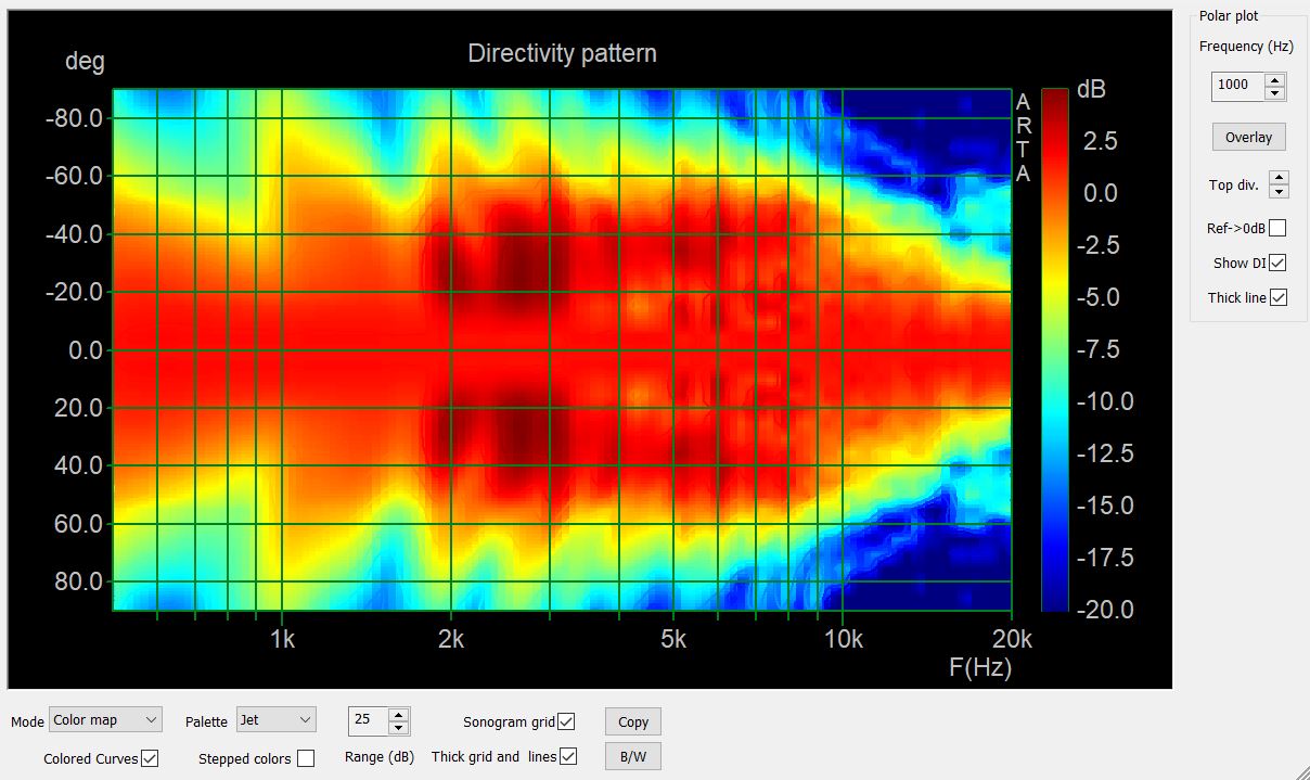
Here are normalised directivity measurements for DE250 in PTWG
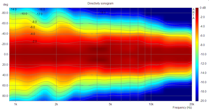
Source: Red Spade Audio: Waveguide shootout 2 - measurements
Source: Red Spade Audio: Waveguide shootout 2 - measurements
Thank you! Their blogpost originally got me into choosing this waveguide. I thought it could be possible to include directivity meassurement data into VituixCAD.
What I do not understand (and maybe someone wants to explain to me):
The JBL waveguide design (in my case copied by Dayton) has been hurrayed for its directivity capabilities, fine. But has ever anyone complained about the resonance/loading issues it has?
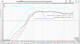
It is visible when it is run without crossover as in Michaels meassurements:
And it obviously does not go away if crossed over to a woofer in a two-way system, because you cannot cross that high.
In a crossover with one notch to controll the lower peaking, there will still be a ditch between 1,7 kHz and and 3,3 kHz, sometimes -5db, other parts -3db. Isn't this a real problem of this CD/wavguide combo?
The JBL waveguide design (in my case copied by Dayton) has been hurrayed for its directivity capabilities, fine. But has ever anyone complained about the resonance/loading issues it has?
It is visible when it is run without crossover as in Michaels meassurements:
Hi sheeple
Just saw your post.
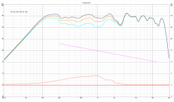
I've attached a new plot of the DE250 with the PH612.
This is the RAW response. No crossover and eq was used.
Taken on axis, mic at 24 inches.
Hope it helps.
Mike
https://www.diyaudio.com/forums/att...3943-de-250-frd-zma-questions-de250_ph612-gif
And it obviously does not go away if crossed over to a woofer in a two-way system, because you cannot cross that high.
In a crossover with one notch to controll the lower peaking, there will still be a ditch between 1,7 kHz and and 3,3 kHz, sometimes -5db, other parts -3db. Isn't this a real problem of this CD/wavguide combo?
Attachments
sheepie,
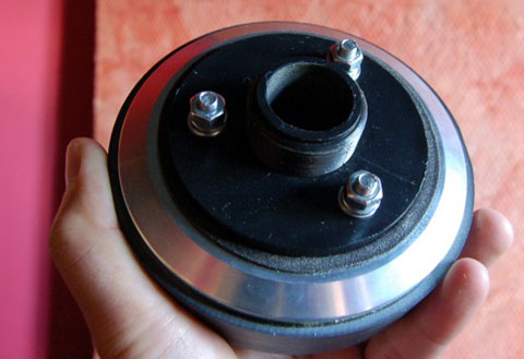
That ( bolt-on to threaded snout ) adapter that you're using introduces some response anamolies all on it's own ( usually in the 2K area ).
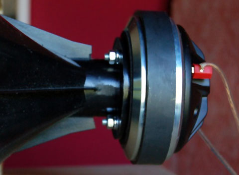
Also, that JBL waveguide produces it's own roller-coaster ( peaks + dales ) to the response ( I think due to the reflective knuckles built into it's expansion profile ).
Lots of people like the sound of these // and that's what's important ( at the end of the day ).
🙂
That ( bolt-on to threaded snout ) adapter that you're using introduces some response anamolies all on it's own ( usually in the 2K area ).
Also, that JBL waveguide produces it's own roller-coaster ( peaks + dales ) to the response ( I think due to the reflective knuckles built into it's expansion profile ).
Lots of people like the sound of these // and that's what's important ( at the end of the day ).
🙂
Thanks Earl! I hope I like the sound, despite of this deep dip. Could I go another way than using a threaded/bolt-adapter, to avoid this? Actually, I was thinking about this myself today, whether the added distance by the adapter could change response.
Or is there simply a better coupling waveguide <-> B&C DE250, that I should consider? I mean: I am investing some money into this build and if this specific waveguide poses such a response problem and another maybe not, I would consider changing.
Or is there simply a better coupling waveguide <-> B&C DE250, that I should consider? I mean: I am investing some money into this build and if this specific waveguide poses such a response problem and another maybe not, I would consider changing.
Last edited:
sheepie,
Lots of people like the sound of these // and that's what's important ( at the end of the day ).
🙂
But you didn't? I found this discussed at audiokarma in 2015 and you recommended the H 290 instead, precisely beacuse it does not introduce such dips in the lower frequencies: Zilch's AK Design Collaborative - Econowave Speaker | Page 793 | Audiokarma Home Audio Stereo Discussion Forums
Also, what is a "bump" filter? I did not understand. Would it help with the Dayton H6512 waveguide?
sheepie,
I listen to Altec 288-8K's on Emilar EH500 radial horns.
I have since around 2003 and don't plan on changing any time soon.
I do own many smaller drivers and smaller horns >> mainly to keep relevant within the conversation ( they are all so inexpensive , really ).
The H290 is a very good performing BiRadial >> though it doesn't get much love ( and I don't really know why ).
I like larger horns . If I was going to stick with the smaller drivers I might try a SEOS 18 (1" entry ).
A "bump-filter" is slang for a 2 or 3-pole "under-damped" HiPass ( mostly ) that EQ's upwards the bottom octave of a driver on a horn ( just before the roll-off kicks in ).
It is very useful when used with these "overly-small" horns and modern compression drivers sporting high Fs figures .
🙂
Huh, staying relevant within conversation is an art on itself, if rightfully executed. Your horns are a bit huge for a city place like mine, though.
Is the B version of the H 290 the same machine as the one without appendix? ATM, it's being sold dead cheap directly by Eminence, on the US market only. I wish they would send it to the EU 🙁
Is the B version of the H 290 the same machine as the one without appendix? ATM, it's being sold dead cheap directly by Eminence, on the US market only. I wish they would send it to the EU 🙁
Yes, the "B" suffix H290 is acoustically identical to the H290 ( no suffix ).
Eminence simply changed some of the assembly details ( around the drivers mounting flange ) . That's about all the difference that I can see .
Here's a pic showing 3 different drivers on one of my H290 horns .

One will not ( typically ) find an Altec driver performing this smoothly on Altec's own "Sectoral" horns .
- The reason for that is the large vanes in the sectorals create chaotic diffraction effects which adversely effect linearity of the response ( seemingly this affects metal diaphragmed drivers the most ).
It's worth reading Joseph Crowe's blog on his results obtained from measuring a TAD 2001 on an Altec 811b vs his own ES-600 BiRadial .
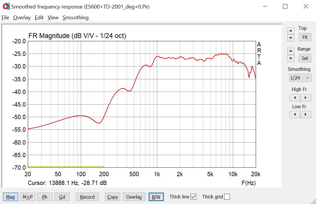
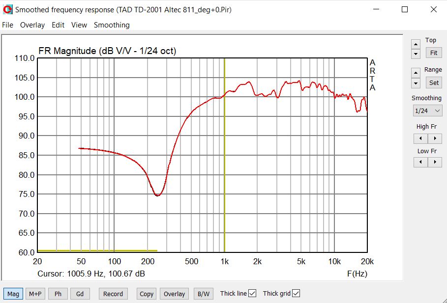
Truly worth noting is that many many people love their 811b horns ( especially in their Altec M19 speakers ) irrespective of any response anomalies ( this fact drives many pure "hornies" nuts ) .
🙂
Eminence simply changed some of the assembly details ( around the drivers mounting flange ) . That's about all the difference that I can see .
Here's a pic showing 3 different drivers on one of my H290 horns .
One will not ( typically ) find an Altec driver performing this smoothly on Altec's own "Sectoral" horns .
- The reason for that is the large vanes in the sectorals create chaotic diffraction effects which adversely effect linearity of the response ( seemingly this affects metal diaphragmed drivers the most ).
It's worth reading Joseph Crowe's blog on his results obtained from measuring a TAD 2001 on an Altec 811b vs his own ES-600 BiRadial .
Truly worth noting is that many many people love their 811b horns ( especially in their Altec M19 speakers ) irrespective of any response anomalies ( this fact drives many pure "hornies" nuts ) .
🙂
Attachments
Last edited:
It may also be an axial resonance. Either way it is much easier to fix than a directivity variation, even though some resonances are simpler to fix than others.better coupling
Hi Allen. What would you suggest to fix it?
If I use two notches and allevate the band, scrape both of the peaks both lower and higher, the dip is neglible and it at least does "look" good simulated. Don't know about directivity: Vituixcad says it is okay, but meassurements will only take place after new year. Another/better idea?
If I use two notches and allevate the band, scrape both of the peaks both lower and higher, the dip is neglible and it at least does "look" good simulated. Don't know about directivity: Vituixcad says it is okay, but meassurements will only take place after new year. Another/better idea?
But isn't the definition of love being truly attached to something profoundly imperfect? 😉Truly worth noting is that many many people love their 811b horns ( especially in their Altec M19 speakers ) irrespective of any response anomalies ( this fact drives many pure "hornies" nuts ).
What would you suggest to fix it?
I'd suggest getting your modelling clay out ( Plumbers//Electricians Mastic ) and adding some tiny "nubs" or bumps within the "straight-pipe" section of your adapter.
The idea is to breakup the standing wave that develops within that straight pipe section.
Since you have measurement capabilities it's a simple matter of "Trial + Error" until you get a trace that's acceptable .
🙂
- Home
- Loudspeakers
- Multi-Way
- B&C DE-250 FRD & ZMA questions