Yes I calculated worst case accuracy by working out how many steps would be off between 7 and 6.98.
The real point is as the stepper can only move in single steps (micro stepping excluded) by having the gear ratio work out to be a whole number of steps or as close to reduces any error from that part of the construction. Given that it is a very simple thing to do I do not see any value in ignoring it.
You are also right that there is plenty of scope for errors to creep in from the physical motion. To me this is another reason to try and keep the easily controlled errors down in the first place.

Sounds like a Hybrid stepper is a consideration. One with a built in rotary encoder. If you are using a belt drive you could also put a rotary encoder on a belt tensioning idler pulley.You are also right that there is plenty of scope for errors to creep in from the physical motion. To me this is another reason to try and keep the easily controlled errors down in the first place.
I'm not so sure about encoders. I know a few people who have had trouble with the implementation of the M1 style ARTA turntable electronics.One with a built in rotary encoder.
The simplicity of the Tic and the basic stepper is nice. It is also very reliable and repeatable which I actually consider to be more important than the ultimate accuracy of position despite what was said above.
I'm sure the mechanical build of the turntable will introduce more error than the stepper itself.
I would note that when a stepper holds at a micro-step interval it tends to make more coil wine. Since this is for sound measurements it probably is good idea to go for full steps (Or use micro-stepping but always hold on a full step).
I still intend to build mine with Marlin. The vast options for 3D printer hardware make will make building all kinds of turntables with it much more easy once implemented in software.
I have a project that uses GRBL, Arduino with CNC shield and two NEMA17 steppers for a turntable. While the steppers behave perfectly and seem to be strong enough, I have failed miserably with the mechanical construction. 6 mm belts and 3D printed toothed wheel were too weak and the teeth on the belt slipped even without any load. I hope with larger gear ratio and 10 mm belts, it will be better. GRBL/Marlin is something I know a bit, so it is relatively easy for me to force the steppers to do what I need by sending Gcode commands.
I'm working on a prototype now 🙂 got a BTT SKR 1.3 board with marlin and a stepper attached. Python script now takes command line arguments and saves to a log file and also connects to control board and issues a currently prr programmed command.
I just need to figure out exactly what commands arta will need to send and then covert to exe.
A nice thing about marlin is it can use s curve acceleration which doesn't wobble the turntable as much. Plus of course TMC silent smooth stepper drives.
I just need to figure out exactly what commands arta will need to send and then covert to exe.
A nice thing about marlin is it can use s curve acceleration which doesn't wobble the turntable as much. Plus of course TMC silent smooth stepper drives.
I believe this should work. It currently turns a motor sitting on the floor 🙂 Connects by USB to the PC and auto detects.
All the setup for the axis itself such as speed, acceleration, limits and homing switches happens in Marlin firmware. There is looooads of videos and guides on setting up Marlin online. A lot of it can be done without having to compile the firmware, just connect to the mainboard using pronterface.exe and set and save the settings.
I'm using the BTT SKR 1.3 that costs about £20. You'll need firmware for it (Marlin) I'll share a compiled firmware later.
If I need to update this once I have built the full turntable I'll let you know.
Attachments
I've experienced the difference between steps and s-curve for a multi-metric-ton rotating device on top of a building. It went from loud bangs and dust falling of lights to whisper quiet operation.
For the stage I'm in tic is more than enough, but I'm always open to better ways.
For the stage I'm in tic is more than enough, but I'm always open to better ways.
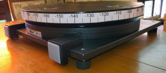
@jcga I hacked together a (half) prototype:

Now I have some additional questions...
Now I have some additional questions...
- Do you have some adjustable feet on the square bottom plate to level it?
- What are the teenuts for?
- How do you attach the top plate? Is it just held in place by some pins and gravity?
- Does your stepper motor also make a lot of noise when moving?
- Where is you power supply located?
- Are the 4 circles with holes in them for cooling?
- Is your stepper mounted to the bracket with 2 bolts only? If not, how did you get the bottom ones in and tightened?
- What do the electrical connections look like? Do you have a panel where you can plug in a usb cable and power for the stepper? Or do you just have some wires permanently attached to the rotation device?
- Do you have any means of adjusting the position of the stepper to make sure the gear is position correctly wrt the 'lazy susan'?
Last edited:
ARTA sends numbers that represent the angle or -r for reset. The exe has to listen for those commands and then send gcode commands for movement in your case.I just need to figure out exactly what commands arta will need to send and then covert to exe.
It will probably be a while before I update again as I've now got to build the hardware. For now, here is the firmware that is working on my test bed for SKR1.3 (I think SKR 1.4 is compatible).
Full source is here. Also the compiled firmware.bin is in the root directory.
https://drive.google.com/file/d/11dgG4Bkclc2os14KJ7GjMvfMFDvsmPmb/view?usp=sharing
Full source is here. Also the compiled firmware.bin is in the root directory.
https://drive.google.com/file/d/11dgG4Bkclc2os14KJ7GjMvfMFDvsmPmb/view?usp=sharing
Sorry for the delay but I was on travel, just back home nowNow I have some additional questions...
Yes
- Do you have some adjustable feet on the square bottom plate to level it?
To fix the bottom plate (18 mm birch plywood
- What are the teenuts for?
Of course not, I Tapped M6 in the original hole of the sleewing ring and top plate (2x18 mm thick) are locked via M6 screws. I did this to easily fine adjust the stepper motor gear
- How do you attach the top plate? Is it just held in place by some pins and gravity?
Yes, quite noisy but it is not a problem for the measurements
- Does your stepper motor also make a lot of noise when moving?
I use an external 9A/12V power bloc from some old laptop (easily found on Ebay)
- Where is you power supply located?
Yes, it is for cooling (not really necessary I think but to stay on the safe side)
- Are the 4 circles with holes in them for cooling?
No, due to the force in presence, I highly recommand to use all the 4. You are right, it's not that easy but it is feasible
- Is your stepper mounted to the bracket with 2 bolts only? If not, how did you get the bottom ones in and tightened?
see pictures
- What do the electrical connections look like? Do you have a panel where you can plug in a usb cable and
The stepper motor is fixed on the bracket, the whole thing is fixed on a 5 mm thick alu plate on the bottom plate in a recess by six scews. Exact position is determined in situ with everything in place but the top plate , the recess depth has to be determined after the slewing ring is fixed. on the bottom ring (2x18mm in my case)
- power for the stepper? Or do you just have some wires permanently attached to the rotation device?
- Do you have any means of adjusting the position of the stepper to make sure the gear is position correctly wrt the 'lazy susan'?
In short I have bottom platform (18 mm), bottom rings (2x18mm), slewing ring, top plate (2x18mm) !
Hope this help
Attachments

Last edited:
Thanks @jcga! I was thinking of 3D printing stuff with places for nuts to be inserted. You've realised the same using teenuts and tapping holes.
I really like 3D printing stuff, but I still have a lot of problems designing stuff in Fusion 360. It's getting better, but even though I think I get the concepts, I just can't seem to actually realise what I have in mind. I was thinking of a circular support below the 'lazy susan' consisting of 3 circle segments that could be customized for a particular preference. So one could choose one segment with just a hole to feed the cabled to the tic or one with a connection plate like yours. Or mounting holes for a connection plate customized for you needs. Banana plugs for a lab power supply, laptop connector for someting like you power supply. And I think it could also simplify mounting all 4 bolts on the servo/bracket. You could first place & tighten those and place the circle segment later giving you better access to the bolts. But up to this point I've mainly been cursing at Fusion....
I really like 3D printing stuff, but I still have a lot of problems designing stuff in Fusion 360. It's getting better, but even though I think I get the concepts, I just can't seem to actually realise what I have in mind. I was thinking of a circular support below the 'lazy susan' consisting of 3 circle segments that could be customized for a particular preference. So one could choose one segment with just a hole to feed the cabled to the tic or one with a connection plate like yours. Or mounting holes for a connection plate customized for you needs. Banana plugs for a lab power supply, laptop connector for someting like you power supply. And I think it could also simplify mounting all 4 bolts on the servo/bracket. You could first place & tighten those and place the circle segment later giving you better access to the bolts. But up to this point I've mainly been cursing at Fusion....
Tom, I'm not sure to fully understand the concept but in my case, I started with the original Arta application note (with the DC motor) first, later I switch to another motor and finally upgraded to the Tic/Stepper/your_soft state.
Again, if I had to start again from scratch, I would certainly use the original Fluid idea: strong enough belt, 3D printed counter plate, Tic/Stepper/soft. Much easier to handle adjustment, quieter, easy to find suitable slewing ring...
Again, if I had to start again from scratch, I would certainly use the original Fluid idea: strong enough belt, 3D printed counter plate, Tic/Stepper/soft. Much easier to handle adjustment, quieter, easy to find suitable slewing ring...
For anyone interested in using ARTA either for this purpose or another and they have been on the fence about getting a licence, time is running out fast
From the ARTA news section
"March, 5, 2024; Important notice:
The lifetime of ARTA development has come to an end.
After more than twenty years of ARTA software development I decided to stop development and take care of myself.
I have fullfilled my promise that ARTA users will get all versions 1.x.x. freely.
Note:
1) ARTA selling will be stopped on March, 30, 2024.
2) The firm ARTALABS be closed in April or May 2024.
3) The ARTALABS web site will be active until February, 2025. The last version and support files will be available for download.
4) I hope that you will be able to use ARTA software on Windows for many years (while Windows support 32-bit programs).
Best regards,
Ivo Mateljan"
Hi Duncan,
Sorry to read this but in all case, as it is now Arta should work fine for quite à long time from now ! at least for automatic polar IMPULSE files measurements...
Sorry to read this but in all case, as it is now Arta should work fine for quite à long time from now ! at least for automatic polar IMPULSE files measurements...
If they won't sell it one would hope it becomes freeware, or it would be such a waste of all the work!
As a licence owner I certianly would not mind.
As a licence owner I certianly would not mind.
I just upgraded my turntable with a NRV30 worm gear, because my speakers are >50kg and the motor didn't have enough torque.Hello! Did you share your project?
I want to do exactly the same - control a stepper motor driven turntable that accepts Gcode commands over USB serial. You used Grbl but I plan to use Marlin firmware on the control board, however both accept Gcode commands.
I have zero coding skills so your Python scripts are foreign to me. Would you be able to help me out with an .exe that accepts the ARTA argument and sends Gcode over serial?
Thanks!
If you want to copy it, get a lazy susan bearing and lasercut gears for it, I used this generator: https://www.festi.info/boxes.py/Planetary?language=en
The big ring goes onto the bearing, the small one on the motor.
Attachments
- Home
- Loudspeakers
- Multi-Way
- Automatic Polar Measurements using ARTA, stepper motor and Tic Controller