I'll have to think about how to do that, I don't have a youtube account or anything similar set up.
Yeah, it would be awfully nice to have.Seems like your lazy Susan is the perfect bed for an automated upgrade 😉
I guess the factors that stop me, are the wide range of size and weights of stuff I've built. I need more sizes of lazy Susans for whole space type meas.
And I've kinda come to the point I don't much care about power response, sticking to measurements that don't don't exceed H-V patterns very much.
It looks like you are planning for some big speakers. How will you handle smaller ones? Pole and a plate?
Yep.Both Arta and rew have multiple measurement modes where the file naming follows the pattern you choose, have you not tried them?
My problem with REW is the use of sweeps. Takes multiples of them outdoors for good SNR given my noisy lake environment.
I've receiving more complaint about the sweeps than outrageously cranking music.
So I use periodic pink and 2-5 seconds time average, which is fine.
ARTA of course has pink, but ime it is cumbersome working with phase given it's 'accept estimated delay' process. Plus, Overlays don't contain phase graphs for quick compares.
Smaart's ability to display real time mag, phase, (and a small Live Impulse) on one screen layout blows ARTA away for convenience.
And it's all in continuous real time, with auto delay tracking if desired.
Plus Smaart handles multiple mic captures and their averaging, each mic with its own delay tracking capability..
So I've come up with a copy, alter, paste workaround for file naming just cause Smaart is so damn easy to use, and nicer to work with in real time.
I'm going to build something like the tripod tower shown in the article I linked before. The Top plate will be small and easy to add larger ones to for bigger speakers. I'll mill a cutout in the columns so that a ratchet strap can be used to hold the bigger speaker to the platform.Yeah, it would be awfully nice to have.
I guess the factors that stop me, are the wide range of size and weights of stuff I've built. I need more sizes of lazy Susans for whole space type meas.
And I've kinda come to the point I don't much care about power response, sticking to measurements that don't don't exceed H-V patterns very much.
It looks like you are planning for some big speakers. How will you handle smaller ones? Pole and a plate?
I decided that it made the most sense to build a strong stable base that did the turning on the bottom rather than trying to do the turning motion higher in the air.
If the filenames from Smaart are consistent you could use an Advanced renamer script to automate the changes. I did that to turn VACS files from 1,2,3 to 0,10,20 etc. You can have multiple scripts for whatever patterns you use.So I've come up with a copy, alter, paste workaround for file naming just cause Smaart is so damn easy to use, and nicer to work with in real time.
https://www.advancedrenamer.com/
I did use ARTA solely to take automatic impulse files nowadays, Don't care to adjust delay to get a proper view of phaseSo I use periodic pink and 2-5 seconds time average, which is fine.
ARTA of course has pink, but ime it is cumbersome working with phase given it's 'accept estimated delay' process. Plus, Overlays don't contain phase graphs for quick compares.
Then, I Use VituixCAS, Tool, Convert IR to FR utility ! Once you have tried this amazing easy utility tool, for sure you will not bother anymore with ARTA way to display frequencies...
I don’t mind the walking back and forth turn the turntable; to take the measurements - just consider it exercise,
what I really dread is everything in between-Setting up, testing connectors, calibrating etc. and packing away again.
because measurements are best down well away from walls, (and due to weather) indoors, everything is setup in the middle of a room.
Which means it’s just eye sore.
Sometimes I just want to walk away and close the door and come back later…

I decided that it made the most sense to build a strong stable base that did the turning on the bottom rather than trying to do the turning motion higher in the air.
Makes good sense to me.
Good tip, thx.If the filenames from Smaart are consistent you could use an Advanced renamer script to automate the changes. I did that to turn VACS files from 1,2,3 to 0,10,20 etc. You can have multiple scripts for whatever patterns you use.
https://www.advancedrenamer.com/
Another good tip, more thx.I did use ARTA solely to take automatic impulse files nowadays, Don't care to adjust delay to get a proper view of phase
Then, I Use VituixCAS, Tool, Convert IR to FR utility ! Once you have tried this amazing easy utility tool, for sure you will not bother anymore with ARTA way to display frequencies...
I'm in the same boat. Manual turntable is easy to do, especially rotating from behind the speaker pointing out from my deck into open space.I don’t mind the walking back and forth turn the turntable; to take the measurements - just consider it exercise,
what I really dread is everything in between-Setting up, testing connectors, calibrating etc. and packing away again.
I can sit on a chair, rotate and capture traces without even moving.
But lugging everything out to the deck, is a pain.
Haha, I don't even close the door.because measurements are best down well away from walls, (and due to weather) indoors, everything is setup in the middle of a room.
Which means it’s just eye sore.
Sometimes I just want to walk away and close the door and come back later…
Lucky my girlfriend doesn't mind stepping over XLR and speaker cables running across the floor everywhere, when i test indoors 😀
Here is the final (I hope) iteration of retrofitting my rotating table. I change the Nema 17 stepper motor + gearbox to a huge and heavy Nema 23 direct drive stepper motor.
I was wondering why I had to adjust the theoretical value for the gear_ratio in the config file to go to the correct position. Error was around 3-4%
The reason was simple, I forgot the fundamental of mechanical engineering : play in the gearbox ! And as it accumulates with number of steps, it's a dead end.
Bingo, with this direct drive stepper motor, everything works as it should, the value to be inserted for the gear_ration is the theoretical value (in my case (177/12 x200/360)
I did several tests from within Arta ( 0 to +/-180° in 5, 10, 30° steps and it always go back exactly to the 0° position by using the "go to zero" button in Arta
I'm happy, the only remaining task will be finish the reinforcement of the supporting gear for very heavy loads. The lazy seven bearing is able to support more than 150 Kg by itself...
Attachments

Jean Claude, that is now a really neat and clean solution and you bought the big Nema 23 too 🙂 I decided to start with the smaller one like I have on my CNC as I will be mounting it the other way. I've hit a few snags printing across the entire bed so my progress has taken a hit.
For anyone that enjoys manually measuring speakers, good for you. I like using a Hand plane but if there's a lot of material to take off the enjoyment fades.
To answer Jean Claude's "challenge" I have created a Youtube account and will upload a video when I can.
For anyone that enjoys manually measuring speakers, good for you. I like using a Hand plane but if there's a lot of material to take off the enjoyment fades.
To answer Jean Claude's "challenge" I have created a Youtube account and will upload a video when I can.
For anyone that enjoys manually measuring speakers, good for you.
Well, yes... I enjoy it, but I do a full set of polar measurements 2 or 3 times per year... if i was doing it every month or every week, I am sure it would get tedious.
At one time (30 years ago) I thought it was great fun to make a frequency response plot by playing 1/3 octave band noise through the speaker, recording the mV reading, converting it to dB, and plotting it on log paper (by hand, with a pencil). Then proceed to the next 1/3 octave band, repeat. repeat. repeat. 30 times... Like I said, it was fun the first time. It was a chore the second time.
So I see your point !
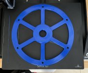
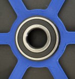
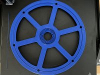
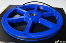
Some progress on printing the gear, bed and fan issues resolved. A successful print of the top piece in PLA+. When warm the bearing can be pushed in for a friction fit. The PETG was a nicer feeling more flexible plastic I think I’ll try the top in that before deciding which way to go.
Concentric support worked quite well for the overhang and was easy to remove. As you can see from the images I couldn’t have made it much bigger.
Concentric support worked quite well for the overhang and was easy to remove. As you can see from the images I couldn’t have made it much bigger.
Attachments

Duncan,
Great work, ingenious use of 3D printing, No, you have no excuse anymore to complete your gear 😊
Dare to see your future Youtube video...
Great work, ingenious use of 3D printing, No, you have no excuse anymore to complete your gear 😊
Dare to see your future Youtube video...
Your wish is my command 🙂Dare to see your future Youtube video...
0 to 180 degree measurement demo
Hall sensor Homing
I tuned the printer but for some reason PETG was a dismal failure separating halfway through so the bottom gear is currently printing in PLA+.
The next printed idea is a degree "tape" 0.5mm thick

The next printed idea is a degree "tape" 0.5mm thick
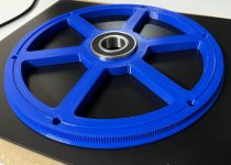
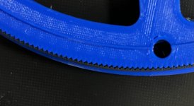
Toothed gear printed without incident and the teeth fit the belt perfectly. Some glue and heat set inserts and this piece will be finished.
Attachments
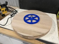
I spent most of the day fixing a stupid mistake I made transferring the centres on the oak discs. The 3D printer saved me with a plug to centre a circle jig so I could cut them down to be the same again. Now the discs are 10mm smaller 🤦♂️
Now I need to devise a mount to hold the aluminium tube square on all sides. The drilled hole was not good enough.
Now I need to devise a mount to hold the aluminium tube square on all sides. The drilled hole was not good enough.
Attachments

We all learned from our mistakes ! At least it obligate us to be creative or tried to be...
Your top plate looks like a piece of furniture 🙂
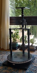
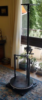
On my side, I have now completed all my retrofitting and upgrade to my existing table, the main constraint was to use the less space possible when not in use (WAF acceptance)
:
I do notice that with the holding torque current, the temp inside the small chamber where the stepper motor reside is getting high (ambient 22°C, inside temp 45-50°C). So even if it is acceptable, I have now four 53 mm diameter ventilation holes that prevent eventual excess temp.
Well, time to go to real stuff now...
Your top plate looks like a piece of furniture 🙂
On my side, I have now completed all my retrofitting and upgrade to my existing table, the main constraint was to use the less space possible when not in use (WAF acceptance)
:
- I double the top plate ans increased a little bit the diameter
- switch from an unreliable DC motor to a very precise stepper motor, again thank you Tom
- re enforce the supporting gear to allow heavy load
- Completely dismount-able in less than 5 minutes
- Full extension 1.70 m
I do notice that with the holding torque current, the temp inside the small chamber where the stepper motor reside is getting high (ambient 22°C, inside temp 45-50°C). So even if it is acceptable, I have now four 53 mm diameter ventilation holes that prevent eventual excess temp.
Well, time to go to real stuff now...
Attachments


I think you'll enjoy the final finish then, even though this is meant to be a tool and not a piece of furniture I like the make it look good if I can.Your top plate looks like a piece of furniture 🙂
The retro fit looks good. How much current did you set to end up with that temperature?I do notice that with the holding torque current, the temp inside the small chamber where the stepper motor reside is getting high (ambient 22°C, inside temp 45-50°C). So even if it is acceptable, I have now four 53 mm diameter ventilation holes that prevent eventual excess temp.
- Home
- Loudspeakers
- Multi-Way
- Automatic Polar Measurements using ARTA, stepper motor and Tic Controller