Just turn the heat sinks upside down leaving the fins in the same direction. That will get some fins in free air not crowded down by the PCB and other components. I say just use the amp if it sounds OK then everything is probably OK. If it sounds bad there still other problems to find. This is where a complete test bench comes into play, test output, distortion, etc. You'll just have to try using it.
Craig
Craig
You might try a big custom chunk of aluminum matching the silk screening and as tall and thick as will fit. Make sure the regs conductive surface is either at same potential or insulated from heatsink. 40C in a to-92 transistor isn't "super" terrible, but how are you measuring? They do make heatsinks for to-92 packages, but plastic doesn't conduct well...
5. Q204 is running at 44ºC (111ºF) and QA204 is running at 39ºC (102ºF). Rest of the Amp is fairly stable at room temp.
How about the other channel? Q104 and QA104, IIRC...
Last edited:
Hello Ron,How about the other channel? Q104 and QA104, IIRC...
I have ordered an IR Thermometer, will arrive today noon. I’ll be posting accurate temps by tonight.
Also working on extending Heatsink sizes. I’ll update soon.
Regards,
Ash
What i am confused with is that if the regs needed heatsinks, why a professional manufacturer such as Audio Source failed to notice it and did not use any.
78XX series regulators have thermal shut down and safe area operation protection that reduces the output voltage/current if exeeded safe limits; and usually work under temperatures as high as you cant touch your finger for long. If can touch it for 15-20 seconds, that means it is most probably under 60 degrees.
I remember you said you had another one same as AS-amp300 working good. I would open it and check the temperatures, input voltage of reg (which was 29V for this one you changed its 7815) and also measure output current, and compare the good and once bad, even though it isworking now after changing the reg in order to make sure everything is ok..
What i am confused with is that if the regs needed heatsinks, why a professional manufacturer such as Audio Source failed to notice it and did not use any.
78XX series regulators have thermal shut down and safe area operation protection that reduces the output voltage/current if exeeded safe limits; and usually work under temperatures as high as you cant touch your finger for long. If can touch it for 15-20 seconds, that means it is most probably under 60 degrees.
I remember you said you had another one same as AS-amp300 working good. I would open it and check the temperatures, input voltage of reg (which was 29V for this one you changed its 7815) and also measure output current, and compare the good and once bad, even though it isworking now after changing the reg in order to make sure everything is ok..
Not a bad idea. I will open the other one on Sunday and compare and revert back,
Regards,
Ash
I think I saw a thread on here where an amp's regulators got hot enough to desolder themselves?
I had an amp on my bench where TO-220 driver transistors had desoldered themselves. You could just pull them right off the board. They had gotten so hot that the board was severely delaminating. And 3 of the 4 output transistors were burnt, because of the driver transistors removing themselves from the circuit.
It's shocking to me how hot some parts get even in a functional circuit. I design around that as much as I possibly can. I would never let a TO-220 package operate at 60-70 degrees C in one of my builds. Service life is derated at higher operating temps.
Just turn the heat sinks upside down leaving the fins in the same direction. That will get some fins in free air not crowded down by the PCB and other components. I say just use the amp if it sounds OK then everything is probably OK. If it sounds bad there still other problems to find. This is where a complete test bench comes into play, test output, distortion, etc. You'll just have to try using it.
Craig
Hello Craig,
Greeting from Toronto.
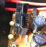
I acted on your advice and made both Heatsinks upside down but added one each heatsink to the opposite side to make these both side finned.
I understand why you asked me to put these upside down.
Yes the heat always travels up. 🙂
Another thing I did is, I replaced both ICs with:
L7915CV-DG ~ IC REG LDO -15V 1.5A TO220 by STMicroelectronics
L7815ABV-DG ~ IC REG LDO 15V 1.5A TO220 by STMicroelectronics
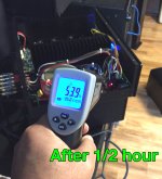
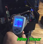
And finally put the Amplifier on test. Its running for past 4 hours.
Temp is stable between 56-57ºC (132-134ºF) even after 4 hours.
AMP is running a full load of 4 ceiling speakers (125W@8Ω each).
Those 4 transistors Q104, QA104, Q204, and QA204 are at 50ºC on both the channels. So planning to put some heatsinks on these 4 transistors.
Your comments please.
Best Regards,
Ash
PS: My sincere thanks to everyone, who helped me to troubleshoot. I really love this forum.
Once again very special thanks to Craig.
Attachments
Last edited:
Amp300 won't startup
Tagging onto this thread, since you gave such great help to the OP.
I have a Amp300 that won't turn-on. Tested the Torrid and I get ~46V and ~22V AC. But where I should get the rectified +/-63Vdc, +/-15Vdc and +24Vdc, I only get ~3.4Vdc (instead of 63Vdc, but it moves around), I get +/-0.0 where I should have +/-15vDC and 0.0 on the 24vDC.
I don't hear the PSU relay "click" on and the front panel LED doesn't come on either. Not sure what it could be, I don't see any obvious burn marks on the PSU board, solder joints all look good. I bought it on eBay, but never been opened before now, had all the lock-tight glue on the screw heads.
Could I have 1, 2 or 3 bad IC's? I know IC01 is a 7815, IC02 is a 7915 and to convert the 24Vdc to +12Vdc IC03 is a 7812. Should I plan on replacing them just to be safe?
I'm also fine replacing all the small capacitors with the IC's. Suggest replacement brand/type for small disk Caps - there are 4-104's and 2-103's? I will probably get Nichicon KA's for the 1000uf/50V and 100uF/25V caps.
Can someone help me with the resistor values for R01/R02? I have attached the schematic, but I don't think "1 1/4w (fuse)" is accurate. And I don't know what "fuse" means or how to order new ones. They both measure OL on my DMM.
R05 measures as the schematic at 10ohm.
R03/R04 - both show 1.5kohm, which matches the schematic.
R06 - measures 4.6k, so very close to spec. too
What about Q01? Chance it's blown? If so, can the replacement be any C1815, TO-92 transistor?
Thanks for the assistance.
Attachments
The high current/voltage supply won't come up until the low current/voltage supply comes up because of the relay. The 1 Ohm 1/4W resistors act as fuses and yours seem to be open and therefore no low supply. Check the bridge rectifier, RD01, and all components up to connector CNB02. Since you are going to have pull the board for the resistors you might as well replace the filter capacitors and the regulators. Install heatsinks on the regs also. After all components are replaced do NOT connect CNB02, check the the low supply for proper voltages first.
Just get some 1 Ohm 1/4 Watt flame proof resistor since they acting as fuses. In your search for you might come across some fusible resistors, order a few extras.
Using your Ohm meter check the other end of CNB02 for shorts/low resistance to ground.
Craig
Just get some 1 Ohm 1/4 Watt flame proof resistor since they acting as fuses. In your search for you might come across some fusible resistors, order a few extras.
Using your Ohm meter check the other end of CNB02 for shorts/low resistance to ground.
Craig
Check the bridge rectifier, RD01, and all components up to connector CNB02.
After all components are replaced do NOT connect CNB02, check the the low supply for proper voltages first.
Using your Ohm meter check the other end of CNB02 for shorts/low resistance to ground.
I just quoted the items I need more info on.
RD01 - how do I check that? Am I just looking for AC on the middle 2 pins and DC on the outer pins?
I have checked every Resistor and it looks like only the 1r 1/4w fuses are OL, but I do plan to buy a few extra (like 10)
I can check the low power supply, makes sense not to mess anything else up until I have verified the correct power is on that connector.
CNB02 - how do I do this? I have check resistance and it is in the 100+kohm region. but it's not working right now, so that might change when I replace some parts? Is that a right assumption, or not?
Thanks for the assist
You're just looking for a short or low resistance on the amplifier side of CNB02, if shorted or low it would explain why the fuse resistors went, +100K is looks OK.
RD01 is just four diodes arranged in square. Two pins should be marked with an AC symbol and the other two + and -. Put your BLACK lead on + and then check both AC pins for normal diode voltage drop, .6 or so. Now put your RED on the - pin and check both AC pins with the BLACK lead, again you should have .6 or so.
Leave the leads in place for several seconds as the filter capacitors may charge up.
Craig
perfect, thanks Craig for confirming for me. I have placed my order at Digi-key and should get Mon/Tues.
I plan to replace all disk, 100uF and 1000uF Caps, the bridge rectifier and both IC's (adding heat sinks to each) as well as the 1r fuse resistors. The other resistors all check out on the DMM and look good.
Will let you know if any issues arise. I will be stoked to get it running again for $20.
Paul
It could as simple as a regulator crapped out and took the fusistors with it. We already know they run on the warm side.
Craig
Craig
I agree that's more than likely what happened, but since the board is out and DigiKey shipping is the same whether I order $5 or $15, I may as well do it all at the same time. Plus I bought heat sinks for my other Amp200 too.
do the heat sinks need some type of thermal paste? if so, recommendations? I have Artic Silver from my computer build if that will work.
do the heat sinks need some type of thermal paste? if so, recommendations? I have Artic Silver from my computer build if that will work.
Thermal compound wouldn't hurt. Arctic Silver is electrically conductive but shouldn't be a problem here as the heatsinks are isolated.
Craig
Craig
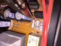
I have a problem...installed all the new components.
Left the amp board unhooked, both low level power connector (CNA02) and the rail supplies (+/- 63Vdc).
Checked all the resistance and power on the low-level connector and the only odd thing was that the -15v was reading -18v and the 24v was 28v.
Figured that was because the relay didn't trip, so maybe current wasn't flowing through everything to drop the voltage down.
Plugged in CNA02 and Rail voltage plugs and turned it on and the front blue LED came on for an instant and then off.
Now the 1r 1/4 watt resistor fuses are blown again.
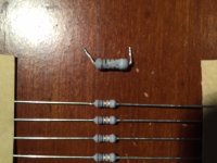
Question - my other AMP200 has the same PSU and those 1r resistor fuses. They appear to be at least 1 watt, not 1/4 watt as in the schematic. Also the ones I removed look to be 1/2 watt
Is there a chance the schematic is wrong and I need 1/2 watt or even 1 watt????
Pics of the comparison, 1/2 watt I removed/replaced is on the top in 1st pic (compared to 1/4 watt) and on left in second pic (compared to AMP200 resistors).
Left the amp board unhooked, both low level power connector (CNA02) and the rail supplies (+/- 63Vdc).
Checked all the resistance and power on the low-level connector and the only odd thing was that the -15v was reading -18v and the 24v was 28v.
Figured that was because the relay didn't trip, so maybe current wasn't flowing through everything to drop the voltage down.
Plugged in CNA02 and Rail voltage plugs and turned it on and the front blue LED came on for an instant and then off.
Now the 1r 1/4 watt resistor fuses are blown again.
Question - my other AMP200 has the same PSU and those 1r resistor fuses. They appear to be at least 1 watt, not 1/4 watt as in the schematic. Also the ones I removed look to be 1/2 watt
Is there a chance the schematic is wrong and I need 1/2 watt or even 1 watt????
Pics of the comparison, 1/2 watt I removed/replaced is on the top in 1st pic (compared to 1/4 watt) and on left in second pic (compared to AMP200 resistors).
Attachments
Last edited:
Ok, since no replies.
I ordered a couple 1/2w, 1w and 2w versions of the 1r resistor (all safety, flame proof type) and Q01 (c1815 - NPN 50V transitor).
Will match the resistor size to my AMP200 and try that one and possibly change out Q01 if someone thinks that is my problem.
I measured all the low-level and Rail voltages of my AMP200, and will compare more closely to ensure they are both very similar before powering up this time.
- Status
- Not open for further replies.
- Home
- Amplifiers
- Solid State
- AudioSource AMP300 Troubleshooting