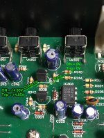
Pin7 of IC303 and pin of CNA02 marked as "GND" (black colored wires) (that you used in your first measurement..)
Pin7 of IC303 and pin of CNA02 marked as "GND" (black colored wires) (that you used in your first measurement..)
Hi nec3,
Thanks again.
Once powered and relays activate, there is DC 0V on Pin7 until relays trip, then it shows DC(+)14.3V. 🙂
Regards,
Ash
Amplifier with DC offset
mukerjea
With all information given until now it look as your power stage have DC offset. To troubleshoot this is a bit difficult as I suppose you will need to turn of the DC protection.
I suggest you to ask help of a friend with more skill in amplifier repair as it is a bit complicated to diagnostic the defective part.🙁
Sorry
Ronaldo
Hi Ronaldo,
Thank you very much for sparing time for me. May be I need to take it to a technician. 😱
Best regards,
Ash
Hi nec3,
Thanks again.
Once powered and relays activate, there is DC 0V on Pin7 until relays trip, then it shows DC(+)14.3V. 🙂
Regards,
Ash
That is what i expected too.
Now, check pins 5 and 6 of the same IC.
Edit: Patience. 🙂
Edit-2: When it trips, short the Base of the Q301 to the ground with a wire. ( OR, you can simply short its base and emitter with a tweezer carefully since its emitter is already connected to GND) and see if the relay releases.

Last edited:
That is what i expected too.
Now, check pins 5 and 6 of the same IC.
Edit: Patience. 🙂
Edit-2: When it trips, short the Base of the Q301 to the ground with a wire. ( OR, you can simply short its base and emitter with a tweezer carefully since its emitter is already connected to GND) and see if the relay releases.
I think i am not allowed to edit a post more than 3 times. 🙂
You can omit "edit-2" since it will most probably not make any difference.
instead, check the B and C voltages of Q301. also when work, when trip.
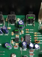
--- If you have a capacitance meter, check C325 and C326 values. ( (when the amp is turned off)) Both are 100Uf. Do this after removing at least one leg of each. If you dont, just replace them with a new one.
---Check the resistance of VR300 (when the amp is turned off)
Last edited:
All right
IC303 at Pin5 - ON is DC 0V and Tripped is DC 0V
IC303 at Pin6 - ON is DC 0V and Tripped is DC 5.45V
Now rest of the test are impossible right now because there is no easy access to the soldering side of the PCB. I’ll have to dismantle whole lot of things to reach the bottom. For this I need time to work on the weekend, if my wife permits 😀
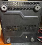
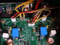
See the images, its a bad design of the AMP that they haven’t given any access from bottom.
IC303 at Pin5 - ON is DC 0V and Tripped is DC 0V
IC303 at Pin6 - ON is DC 0V and Tripped is DC 5.45V
Now rest of the test are impossible right now because there is no easy access to the soldering side of the PCB. I’ll have to dismantle whole lot of things to reach the bottom. For this I need time to work on the weekend, if my wife permits 😀
See the images, its a bad design of the AMP that they haven’t given any access from bottom.
Attachments
All right
IC303 at Pin5 - ON is DC 0V and Tripped is DC 0V
IC303 at Pin6 - ON is DC 0V and Tripped is DC 5.45V
Now rest of the test are impossible right now because there is no easy access to the soldering side of the PCB. I’ll have to dismantle whole lot of things to reach the bottom. For this I need time to work on the weekend, if my wife permits 😀
See the images, its a bad design of the AMP that they haven’t given any access from bottom.
Pin 5 should be 7,5 V. Check R345 and R345 values. Solderings for cold joint.
You almost found the problem.
Check the resistance between 5 and ground.
For Q301 B and C check, you canmake tests from component side at the resistance legs going to the transistors. (R338, 339)
Last edited:
Are looking for a problem in the protection circuit? Looks like the protection circuit is working because you have too much DC offset in both channels. You need to find why both channels have the same offset, it must be a common problem to both channels. Check all of your DC supplies for starters. Are you sure of the polarities of the offset, they are opposite?
Craig
Craig
Sorry! There was typing error by me. Actual readings at the speaker post areAre looking for a problem in the protection circuit? Looks like the protection circuit is working because you have too much DC offset in both channels. You need to find why both channels have the same offset, it must be a common problem to both channels. Check all of your DC supplies for starters. Are you sure of the polarities of the offset, they are opposite?
Craig
Speaker Right Channels A or B set shows DC (+)0.003V slowly goes up to DC(+)0.006V
But strangely:
Speaker Left Channels A or B set shows DC (-)0.003V slowly goes up to DC(-)0.006V
Then, I tested Mono Bridged mode too.
That is also showing DC( -)0.003V slowly goes up to DC(-)0.006V
Thanks for pointing out my goof-up. 😀
Wow, that's a whole lot of difference. So, the amp works for a few minutes and then the speaker relay de-energizes for no good reason. Back to the schematics I go.
Craig
Craig
Last edited:
Pin 5 should be 7,5 V. Check R345 ..... side at the resistance legs going to the transistors. (R338, 339)
Value of R345 = 6.13kΩ (Power OFF)
IC303
Resistance between Pin5 and GND = 6.12kΩ (Power OFF)
Q301
At Base - ON = 0V, Trip = when it trips it shows 6.7V and rapidly goes down to 0V
At Collector - ON = 14.90V and Trip = when it trips it shows 6.0V and rapidly goes back up to 14.90V
Attachments
Wow, that's a whole lot of difference. So, the amp works for a few minutes and then the speaker relay de-energizes for no good reason. Back to the schematics I go.
Craig
Hi Craig,
Thats correct. Load or no load. When the Amp is cold (first time) It takes longer to trip, about 4-5 minutes.
Second time and every time after that, it takes about 1-2 minutes to trip.
Regards,
Ash
OK, there are three relays in this amp. One for the high current voltage for the amplifier circuit, one for the input signal detection and the last one for speaker protection. Which one is de-energizing after the short time period?
Craig
Craig
Value of R345 = 6.13kΩ (Power OFF)
IC303
Resistance between Pin5 and GND = 6.12kΩ (Power OFF)
Q301
At Base - ON = 0V, Trip = when it trips it shows 6.7V and rapidly goes down to 0V
At Collector - ON = 14.90V and Trip = when it trips it shows 6.0V and rapidly goes back up to 14.90V
B voltage is probably 0.67V , not 6.7V.
Anyway,
Make a connection from pin-3 of IC303 to the GND with a short wire and see if the amp works OK.
OK, there are three relays in this amp. One for the high current voltage for the amplifier circuit, one for the input signal detection and the last one for speaker protection. Which one is de-energizing after the short time period?
Craig
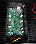
When the Amp trips, For both channels DC 64V supply remains on.
See the pic. These 2 Blue relays seems to be tripping.
Ash
Attachments
B voltage is probably 0.67V , not 6.7V.
Anyway,
Make a connection from pin-3 of IC303 to the GND with a short wire and see if the amp works OK.
I’ll recheck the voltage. When should I make the connection? After the Amp trips?
OK, those are the speaker relays. Since both relays are de-energizing it has to be something common to both channels. Check your +/- 15 VDC supplies and the +24 VDC supply.
Craig
Craig
If I am getting you correctly,When it is turned off. Then, turn on and see if it works good or no change.
I should turn on the Amp first and when it trips, I make the GND-Pin 3 connection and re-power the AMP with wire attached and see if it trips again or not? How long should I wait if its not tripping?
- Status
- Not open for further replies.
- Home
- Amplifiers
- Solid State
- AudioSource AMP300 Troubleshooting