If I am getting you correctly,
I should turn on the Amp first and when it trips, I make the GND-Pin 3 connection and re-power the AMP with wire attached and see if it trips again or not? How long should I wait if its not tripping?
No.
Make the connection when the amp is power off. Then turn on and check if it still trips.
OK, those are the speaker relays. Since both relays are de-energizing it has to be something common to both channels. Check your +/- 15 VDC supplies and the +24 VDC supply.
Craig
Hi Craig,
I found something interesting.
+24 Volts supply is 27.6V and remains same after tripping.
+15 Volts supply is 14.96V and remains same after tripping.
-15 Volts supply is -11.96V and starts going down before the Amp trips and around -9.65V it trips then voltage goes further down to 0.0V and then (+)0.007V.
Regards,
Ash
There's your problem, you're losing -15VDC. With the amp turned on put your finger on each of the opamps, one of them hotter than the rest? Either the voltage is being loaded down or the reg. IC is bad.
Craig
Craig
There's your problem, you're losing -15VDC. With the amp turned on put your finger on each of the opamps, one of them hotter than the rest?
Craig
A newbie question:
Which are the opamps, the ones which are mounted with big heatsink?
There's your problem, you're losing -15VDC. With the amp turned on put your finger on each of the opamps, one of them hotter than the rest? Either the voltage is being loaded down or the reg. IC is bad.
Craig
Good job..! So he will not have to go to repairshop.
Congratulation 🙂
And, my prediction with the line switching circuit was wrong.
Good job..! So he will not have to go to repairshop.
Congratulation 🙂
And, my prediction with the line switching circuit was wrong.
Hi,
You are the one who kept this Post alive, otherwise I had lost hopes to repair it ever.
I am really thankful to you and still I’ll be needing your help.
Best regards,
Ash
Opamps are the little square black things with 8 pins, 4558 etc.
Craig
Oh! OK. I’ll revert back once I figure it out the hot one 🙂.
Then you can guide me further on it.
I really appreciate your help to troubleshoot the problem.
Best regards,
A Happy “Ash” 😀
Opamps are the little square black things with 8 pins, 4558 etc.
Craig
Hi Craig,
I don’t think the problem is with these opamps. These are all running cold.
Please advise.
Ash
IC02 is the -15VDC regulator, a 7915 reg. It supplies ALL of the ICs, you do can two things, replace the 7915 IC to see if it fixes it OR remove each of the opamps, 4558, etc. one by one until the -15VDC comes back. I don't know your skill level so I'll leave the decision up to you. Replacing the 7915 IC would be quickest and easiest.
Another way is to unplug connectors while monitoring the -15VDC with your meter, that will eliminate some of the opamps.
Craig
Another way is to unplug connectors while monitoring the -15VDC with your meter, that will eliminate some of the opamps.
Craig
Last edited:
Disconnecting CNB02 would completely isolate both regulators. CNA02 would eliminate the power amp section. CNA302 would eliminate the input board.
Craig
Craig
Disconnecting CNB02 would completely isolate both regulators. CNA02 would eliminate the power amp section. CNA302 would eliminate the input board.
Craig
Hi Craig,
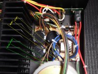
I disconnected CNA02 and eliminated power amp section. See the pic attached.
-15V started with -12.40V and started falling on its own. In 35 minutes it went down to -11.72V. It was still falling slowly when I switched off the AMP.
I think IC02 has gone weak or gone bad because after the above, I disconnected CNA302(input section), and powered the AMP, It tripped again like always. May be IC02 is not able to handle the load.
Since, I have to replace IC02, smight well replace IC01 too.
Any other part in power section to be replaced?
Which Brand ICs should I buy and what numbers?
Thanks again,
Regards,
Ash
Attachments

Measure pin 2 of IC02 to make sure the correct input voltage is there. It should be the same as pin 1 of IC01 but opposite polarity. Also just by chance C06 and/or C08 could be bad. How easy would it be to pull one leg of either of those capacitors? If the voltage on pin 2 of IC02 is good and both capacitors isolated and the voltage is still bad IC02 must be bad.
Craig
Craig
Measure pin 2 of IC02 to make sure the correct input voltage is there. It should be the same as pin 1 of IC01 but opposite polarity. Also just by chance C06 and/or C08 could be bad. How easy would it be to pull one leg of either of those capacitors? If the voltage on pin 2 of IC02 is good and both capacitors isolated and the voltage is still bad IC02 must be bad.
Craig
Hi Craig,
This Amp has no access to the soldering side of the PCB. For this I will have to take the power board out and do it. I can do it but dare not power it when the board is hanging out.
I can initially, Check Pin2 of ICO1 and IC02 as is. Is Pin2, the center pin?
Ash
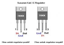
Looking at the face of the device left to right, 1,2,3. The 78xx series, +, are easy to remember, input on the left, output on the right. The 79xx series, -, are different.
Units without removable bottom covers suck the big one. Absolutely a PITA to work on.
Craig
Units without removable bottom covers suck the big one. Absolutely a PITA to work on.
Craig
You got it.
Craig
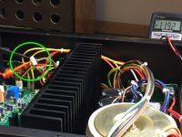
I checked the voltages.
Transformer wires are Blue/Black/Blue – 46.9V and 47.0V
Secondary wires are Brown/Black/Brown – 21.5V and 21.5V See image
Input Voltage at IC01 7815 ~ (+)28.9V
Input Voltage at IC02 7915 ~ (–)29.0V
Attachments
Last edited:
OK, one last test before we commit the regulator. Measure the resistance, Ohms, on that connector you measured the BAD voltage. Power OFF, measure from the the -VDC pin to ground, red lead on grd. This will rule out shorted capacitors on the output of the reg.
Craig
Craig
OK, one last test before we commit the regulator. Measure the resistance, Ohms, on that connector you measured the BAD voltage. Power OFF, measure from the the -VDC pin to ground, red lead on grd. This will rule out shorted capacitors on the output of the reg.
Craig
You mean on connector CNA02 between pin 4 and 6?
If this is correct then, with RED wire on ground Pin 6 and black on pin 4.
Resistance is 19.06kΩ
Attachments
Last edited:
- Status
- Not open for further replies.
- Home
- Amplifiers
- Solid State
- AudioSource AMP300 Troubleshooting